TVS Diodes

TVS (transient voltage suppressor) diodes are used to protect circuit board traces from high voltage spikes. They are designed to be operated in the reverse direction and work by shunting currents when the reverse voltage exceeds the avalanche breakdown potential. They are basically high-power Zener diodes, and are a specialized form of an avalanche diode.
They are part of a family of components used for ESD (electro-static discharge) protection, which also includes Zener diodes (however, ESD is not the only thing Zeners are used for). TVS diodes can handle large amounts of peak power (hundred’s or thousands of Watts), but Zeners have a tighter voltage tolerance. TVS diodes have more capacitance than Zeners, which could be detrimental in some circumstances (e.g. when protecting the gate signal on a MOSFET).
They come in either uni-directional or bi-directional flavours. Uni-directional TVS diodes block up to the rated voltage in one direction, and behave like a normal conducting diode in the other. Bi-directional block up to the rated voltage in both directions (good for protecting AC waveforms). Use uni-directional diodes if possible, they are cheaper, and they have much faster turn-on times than their bi-directional counterparts (e.g. 4ps compared to 4ns).
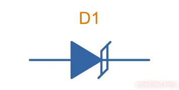
Schematic Symbol
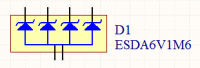
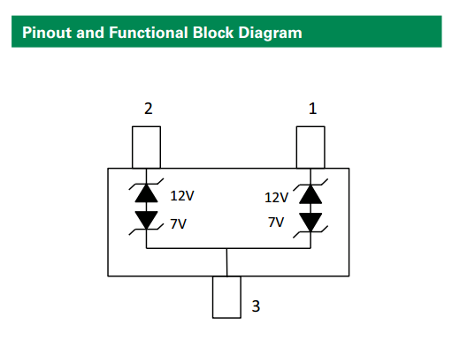
Arrays
TVS diodes can be grouped into IC packages called arrays. A typical schematic symbol for a diode array is shown below.
Important Parameters
Breakdown Voltage
- Symbol:
- Units:
Also called the reverse breakdown voltage. This is the reverse voltage (cathode-to-anode) at which the diode “begins” to conduct. The point at which the diode begins to conduct is usually specified as a fixed current, typically 1mA.
Rated Power
- Symbol:
- Units:
The maximum power the TVS diode can dissipate, for a specified time period. Typical values range between 400W-1.5kW.
Standoff Voltage
- Symbol: ,
- Units:
This is the reverse voltage that the diode can withstand without drawing “any” current. This is one of the most important parameters, as you usually match this voltage to the maximum operating voltage of the wire you are connecting it to. Note that there is a small amount of current drawn at this voltage, this is called the reverse leakage current.
Vishay uses the symbol to denote the standoff voltage.1
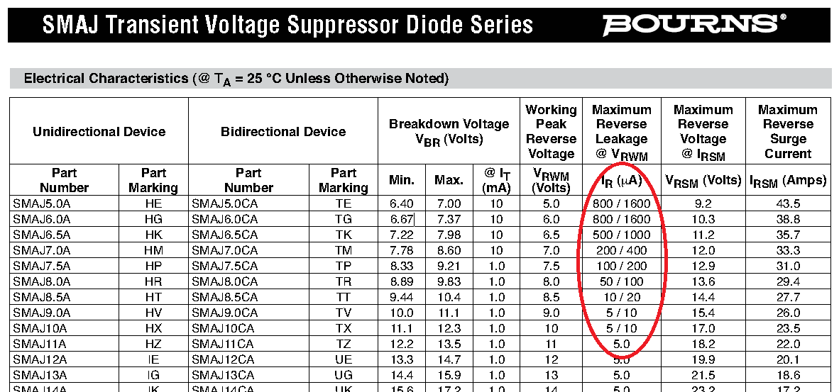
Leakage Current
The reverse-leakage of TVS diodes decreases as the stand-off voltage increases. Be warned, the leakage current of TVS diodes which have low voltage stand-offs (e.g. <10V), can have large leakage currents! A 5V stand-off TVS diode typically has a reverse-leakage current of around 500uA, but TVS diodes with a stand-off voltage of 10V or higher have a reverse-leakage of 1uA or less. Note that at low stand-off voltages, the leakage current of a bi-directional diode can be double that of a uni-directional diode for the same stand-off voltage.
For more information, see the ESD Protection page.
Reverse Polarity Protection
Unusually, TVS diodes. along with a fuse or other current-limiting device, can act as a very good reverse-polarity protection mechanism on inputs to a PCB. They are usually present on a voltage rail input for the primary reason of reducing ESD. However, if the V+ and GND are connected to the PCB the wrong way around, the TVS diode will forward conduct and clamp the voltage to a normally non-destructive 0.7-1.5V. A current-limiting device like a fuse also has to be present to prevent the TVS diode from overheating.
They are especially suited to this role (when considering other diodes) as the are usually built to dissipate large amounts of heat.
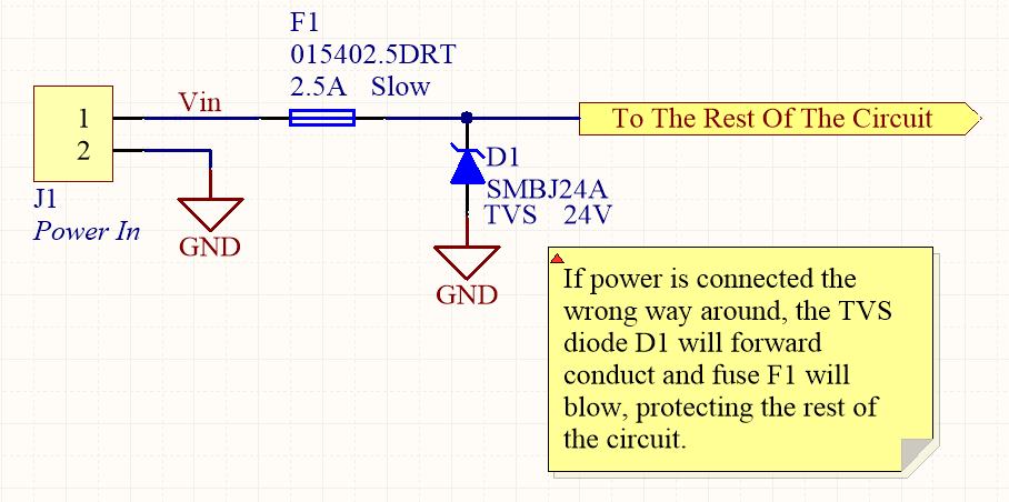
In the schematic above, the fuse will quickly blow if the power supply is connected to the input connector the wrong way around.
Low Capacitance
There are a family of TVS diodes called low-capacitance (or ultra-low) TVS diodes. They have much less capacitance than standard TVS diodes (typical capacitances are between 0.4-0.9pF), and are designed for protecting high-speed data lines such as those used in USB, HDMI, DisplayPort, and Ethernet communication protocols and also for RF antennas such as GPS, FM radio and NFC antenna lines.
This low capacitance is achieved by adding a forward-biased general purpose diode in series with the usual reverse-biased TVS (zener-style diode). The schematic symbol for a low-capacitance TVS diode is shown below:
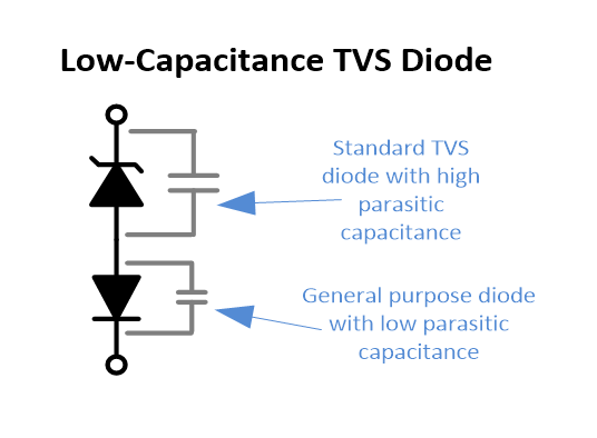
The forward-biased general purpose diode has a much smaller parasitic capacitance than the zener diode. Because the parasitic capacitances are in series (grey capacitors in diagram), the total capacitance of the component is greatly reduced!
Reducing TVS Capacitance Manually
High power TVS diodes have a significant amount of capacitance. For example, the Wurth Elektronik 824541361 is a 36V 1500W TVS diode with a capacitance of approx. 700pF at 24V. This can be too high for some applications in where you are protecting high-speed data lines. And there may be no single TVS diode component option which provides both the high power absorption and low capacitance you require. In this case, one trick is to add standard general purpose diodes in series with the TVS diode. This is a placeholder for the reference: fig-manual-low-capacitance-tvs-trick-on-wurth-elektronik-spe-with-podl shows this trick being used (see red circled components) to reduce the capacitance of TVS diode in a Single Pair Ethernet (SPE) system with Power over Data Lines (PoDL).
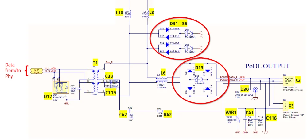
The low capacitance of the general purpose diode when in series with the TVS diode makes the total capacitance much lower (assuming the GP diode has a much lower capacitance, the total capacitance will only be slightly higher than the capacitance of general purpose diode itself due to the law of series capacitance).
Snapback Type TVS Diodes
Snapback TVS diodes are a type of TVS diode in which the clamping voltage right after triggering is less than the trigger voltage (a form of foldback). This is to provider a harder “turn-on” characteristic and results in the voltage not creeping as far above the reverse standoff voltage than with a conventional TVS. Snapback can either be shallow or deep, depending on the application. Shallow snapback can be achieved with a standard TVS diode connected in parallel with a BJT. Deep snapback can be achieved with a self-triggering thyristor circuit.3
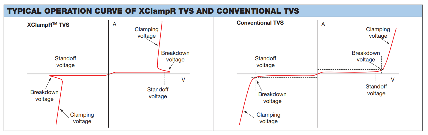
The Vishay XLD5A24CA is an example of a snapback TVS from Vishay’s XClampR series. Is had a standoff voltage and a clamping voltage at ( waveform)1. Note the clamping voltage is much closer to the standoff voltage than a conventional TVS!
Automotive Load Dump Clamping
TVS diodes can be used to clamp the nominally +12V rail in automotive applications.
Load-dump TVS diodes are designed to protect systems when the alternator is running and the battery is suddenly disconnected5. When this happens a large positive going voltage spike can occur on the +12V rail. The spike is worst when the battery is significantly discharged.
Why does this happen? When the battery is very flat, the alternator is generating a large amount of current to charge the battery. When the battery is suddenly disconnected, the load on the alternator suddenly decreases. The field windings which are used to regulate the alternators output current have a significant inductance to them. Because of this inductance, the control circuitry cannot reduce the field winding current fast enough, the alternator starts producing too much energy and thus a large voltage spike occurs on the output[^wikipedia-load-dump].
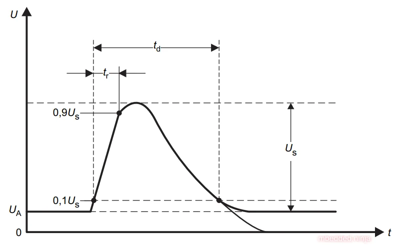
A “standard” load-dump surge which TVS diodes can be rated to (and products tested against) is defined in ISO16750-2.6
ISO7637-2 is an older standard which defines only 1 pulse. ISO16750-2 is a newer standard which 10 pulses in 10 minutes. It also defines a higher Us and larger voltage range.5
Special-Purpose TVS Diodes
RS-485 TVS Diodes
TVS diodes built specifically for protecting RS-485 communication protocol bus lines are bi-directional and have two different hold-off voltages to meet the RS-485 spec. They normally include the character sequence “SM712” in their part name (e.g. SM712-02HTG by Littelfuse and SM712-TP by Micro Commerical).
More information on these diodes can be found in the Specialised TVS Diodes section on the RS-485 Protocol page.
Footnotes
-
Vishay (2022, Dec 1). XLD5A24CA - Surface Mount XClampRTM Transient Voltage Suppressors (datasheet). Retrieved 2023-05-30, from https://www.vishay.com/docs/87199/xld5a24ca.pdf. ↩ ↩2
-
Wurth Elektronik. Reference Design RD041 - Design of a Single Pair Ethernet System with Power over Data Lines (SPoE). Retrieved 2025-10-28, from https://www.we-online.com/files/pdf1/rd041b_design-of-a-single-pair-ethernet-system-with-power-over-data-lines-spoe-v1.pdf. ↩
-
Bill Russell (2020, Mar 18). TVS? It’s Just a Diode, Right? Part Two. Semtech. Retrieved 2023-05-30, from https://blog.semtech.com/tvs-its-just-a-diode-right-part-two. ↩
-
Vishay (2022). Did you know? - Industry-first Snapback Type XClampR™ TVS. Retrieved 2023-05-30, from https://www.vishay.com/docs/48799/ms26900578_did_you_know-xclampr_tvs.pdf. ↩
-
Littelfuse. TVS Diodes to Meet Automotive Load Dump Standard. Retrieved 2024-08-06, from https://m.littelfuse.com/~/media/electronics/application_notes/littelfuse_tvs_diode_meet_automotive_load_dump_standard_application_note.pdf.pdf. [^wikipedia-load-dump]. Wikipedia (2023, Dec 4). Load dump. Retrieved 2024-08-07, from https://en.wikipedia.org/wiki/Load_dump. ↩ ↩2
-
Diodes Incorporated. DM5WxxAQ, DM6WxxAQ, DM8WxxAQ - Automotive-Grade DO-218 Load Dump TVS Series. Retrieved 2024-08-06, from https://www.diodes.com/assets/product-showcases/Automotive-Grade-DO-218-Load-Dump-TVS-Series-Diodes-NPA-052019.pdf. ↩
-
Atul Singh (2015, Mar). SNVA681A - Application Report - Load Dump and Cranking Protection for Automotive Backlight LED Power Supply. Texas Instruments. Retrieved 2024-08-07, from https://www.ti.com/lit/an/snva681a/snva681a.pdf. ↩