Ethernet Protocol

History
Ethernet is largely considered invented by Bob Metcalfe and David Boggs in 1973 at Xerox’s Palo Alto Research Center (PARC). The name “Ethernet” comes from the concept of the aether — a medium once thought to carry light waves. It was inspired by ALOHAnet, a network designed in the late 1960s at the University of Hawaii.1 The system that Bob and David setup in 1973 connected local computers together at Xerox.
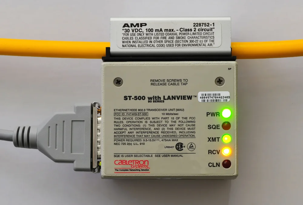
In 1980, the first standardized (and commercialized) version of Ethernet, 10BASE5 (“Thicknet”) was released (called the DIX standard, made bu DEC, Intel and Xerox). IEEE then ratified it as 802.3 in 1983. It was built with stiff yellow coax cable approx. 9.5 mm in diameter. The name comes from the fact it was 10 Mbps and the cable could be up to 500 m long. Nodes were attached with N connectors or tapped into in with a vampire tap, a clamp with a needle that pierced the cable without cutting it. 10BASE2 (“Thinnet”) was a thinner, cheaper coax cable terminated with BNC connectors.
Components
Connector
RJ45 jack. Technically it’s not actually an RJ45 connector, but an 8P8C (8 position, 8 contacts) connector. RJ45 is actually a now defunct 2 wire connector designed for modems. These days, RJ45 is effectively slang for all ethernet style connectors. Connectors which integrate the magnetics are called integrated connector modules (ICMs).
There are two common pinouts for the RJ45 connector:
- T568A:
- T568B:

Magnetics
Magnetics are part of the Ethernet specification for all xBASE-T networks (which includes pretty much every Ethernet PHY standard except for the first StarLAN-1, StarLAN-10 and LattisNet).
There are two options for magnetics, either:
- Buy a ethernet magnetics component for your PCB.
- Buy a jack (connector) which already has the magnetics integrated into it. Connectors which integrate the magnetics are called integrated connector modules (ICMs).
Physical Layer (PHY)
The PHY is the circuitry which drives the magnetics.
MAC
Standards
Many of the IEEE Ethernet standards are in a form similar to 10BASE-T. In this example, the 10 represents a throughput of 10 Mbps, BASE is because it uses baseband transmission (the twisted pairs can transmit frequencies all the way down to DC), and the T indicates the transmission medium used.3 G is added to the throughput to indicate Gbps, e.g. 5GBASE-T is a throughput of 5 Gbps.
10BASE-T
Used Cat 3 cable.
10BASE-T1L
Designed for automotive and IoT applications.
10BASE-T1S
Designed for automotive and IoT applications. Allows for a multi-drop architecture.
Ethernet Jacks
Some ethernet jacks come with the magnetics already in-built, saving you the trouble of including them yourself on the mounted-to PCB
Power Over Ethernet (PoE)
Power over Ethernet (PoE) is the term used to describe ethernet cables/systems that also provide a power source over the same cable as the data. Typically 44-57VDC (48V is a common choice) is passed over one or more of the twisted pairs in most ethernet cables. Data and power can be transmitted along the same twisted pairs as long as proper transformer-based extraction (center-tapped isolation transformers) of the AC data signal and DC power is used. The early PoE standards could provide around 10W of power, but the newer standards allow up to approx. 75W.
Power sourcing equipment (PSE) are the devices that provide power onto the ethernet bus. The powered device (PD) is the device on the other end of the cable which is consuming the power. The PDs can be up to 100m away from the PSE (as defined by the existing Ethernet standard, this is unchanged with the introduction PoE).
A PoE injector is a stand-alone device used to add (“inject”) DC power into an existing Ethernet cable.
The assured power is the amount of power available to the powered device at the end of cable. This is less than the power outputted by the PSE due to the energy lost in the impedance of the cabling.
| Name | IEEE standard | Year | Power to PD | Max. power per port | Energized pairs | Supported devices |
|---|---|---|---|---|---|---|
| PoE | IEEE 802.3af (Type 1) | 2003 | 12.95 W | 15.4 W | 2-pair | VoIP phones, WAP |
| PoE+ | IEEE 802.3at (Type 2) | 2009 | 25.5 W | 30 W | 2-pair | |
| PoE++ (UPoE) | IEEE 802.3bt (Type 3) | 51 W | 60 W | 4-pair | ||
| PoE++ | IEEE 802.3bt (Type 4) | 71.3 W | 100 W | 4-pair | Tilt/pan/zoom (PTZ) security cameras. |
PoE++ is also known as 4PPoE. UPoE is an acronym for Ultra Power over Ethernet.
Signature resistance of 25kR.
Single Pair Ethernet (SPE)
Single Pair Ethernet (SPE) is a version of Ethernet which uses a single twisted pair. Coupled with PoDL (Power over Data Lines), it is impressive that a single twisted pair can be both used to send bi-directional data (~10Mbps) and power (~50W) over the same cable!
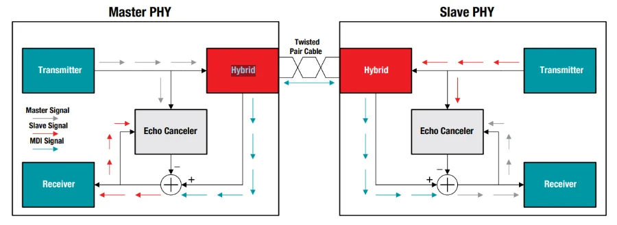
Bi-directional data over the same pair works by the principle of superposition. Each side has echo cancellation which is used by their receiver to cancel out their own transmitted signal, leaving behind the component of the waveform which was sent from the other side.4
All SPE standards have -T1 in their name, since the 1 refers to a single twisted pair.
| Year | Standard | Speed | Max. Distance | Symbol Rate | BER | Duplex | PoDL | ||
|---|---|---|---|---|---|---|---|---|---|
| 2019 | IEEE 802.3cg | 10BASE-T1S | 10 Mbit/s | 25 m | UTP | 12.5 MHz | 1 x 10⁻⁹ | HD | No |
| 10BASE-T1L | 1000 m | STP | 7.5 MHz | 1 x 10⁻¹⁰ | FD | Yes | |||
| 2015 | IEEE 802.3bw | 100BASE-T1 | 100 Mbit/s | 15 m | UTP | 66.6 MHz | |||
| 25 m | STP | ||||||||
| 2016 | IEEE 802.3bp | 1000BASE-T1 | 1000 Mbit/s | 15 m | Type A | 750 MHz | |||
| 40 m | Type B | ||||||||
| 2020 | IEEE 802.3ch | 2.5GBASE-T1 | 2.5 Gbit/s | 15 m | STP | 1.4 GHz | |||
| 5GBASE-T1 | 5 Gbit/s | 2.8 GHz | |||||||
| 10GBASE-T1 | 10 Gbit/s | 5.6 GHz | |||||||

In SPE, each node in the bi-directional link must be configured as either the master or slave. This is a PHY level role that is needed so that the echo cancellation can be correctly implemented. The master provides the clock reference and transmits it using its local oscillator. The slave recovers the clock from the master’s signal and uses that clock to time its own transmissions. For 100BASE-T1, these roles have to be manually configured (usually by a jumper, DIP switch or register setting on the PHY on each end). 1000BASE-T1 and newer standards have added auto-negotiation to determine the role of each node automatically at connection time.
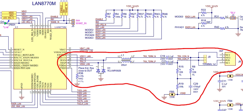
Below is a schematic of a 100BASE-T1 PHY on the Microchip EV02N47A LAN8770M converter board (PHY part circled in red). You can see magnetics are not used here, but instead capacitive coupling (the only inductor looking thing is a common mode choke). C19 and C20 are the two small (100nF) blocking capacitors. You do lose galvanic isolation with capacitive coupling, but it makes the design simpler, smaller and cheaper.
PAM3
PAM3 is a pulse amplitude modulation scheme which uses three different voltage levels to encode data. It is used by the mid-range SPE standards 10BASE-T1L, 100BASE-T1 and 1000BASE-T1. Each PAM symbol is represented by one of three voltage levels:
- +1V: a positive voltage relative to the common-mode level.
- 0V: zero differential voltage.
- -1V: a negative voltage relative to the common-mode level.
Each PAM3 symbol carries bits of information. In practice, standards layer a whole-bit encoding on top of the raw symbols — 100BASE-T1 uses 3B2T, which maps 3 binary bits onto 2 ternary symbols (an effective 1.5 bits per symbol). These two ternary symbols which represent 3 bits of data are called a code group.7
PAM3 sits between NRZ (binary, 1 bit per symbol) and PAM4 (quaternary, 2 bits per symbol) in the trade-off between symbol rate and noise margin. Compared to NRZ, PAM3 roughly halves the symbol rate needed for a given data rate, at the cost of a tighter noise margin per level — each level has half the voltage headroom before it gets confused with its neighbour. Going further to PAM4 halves the symbol rate again but is more sensitive to noise and crosstalk, which is why it only becomes worthwhile at multi-gigabit speeds.
100BASE-T1 Link Start-up and Handshaking
When 100BASE-T1 devices are powered up, they need to go through a start-up/training process. During this process, the master and slave can be in one of the following states:7
- SEND_Z: The transmission of all zeros (called zero-codes).
- SEND_I: The transmission of PAM3 idle signals.
- SEND_N: The transmission of PAM3 data or idle signals.
The following process is used to start up the link:7
-
Master SEND_Z, slave SEND_Z
Both master and slave start by transmitting all zeros (SEND_Z).
-
Master SEND_I, slave SEND_Z
The master transmits PAM3 idle signals (SEND_I) while the slave transmits all zeros (SEND_Z). This allows the master to train its echo canceller, while the slave synchronizes to the master’s clock, locks its scrambler and adjusts its signal conditioning.
-
Master SEND_I, slave SEND_I
The slave then transitions from SEND_Z to SEND_I. The master stays in SEND_I mode. This allows the slave to train its echo canceller, while the master locks its scrambler and adjusts its signal conditioning.
-
Setting status
The master and slave set status flags. If these statuses are validated, then both master and slave switch to SEND_N. If any statuses fail, the link startup process resets.
Automotive Ethernet
Automotive Ethernet (formerly called BroadR-Reach or OABR (Open Alliance BroadR-Reach)) can be thought of as a subgroup of SPE. It uses the same single twisted pair cable, but defines additional high-level protocols on top of the SPE protocol.8
It is a popular choice for automotive applications which is gaining momentum against the more traditional CAN bus for the backbone of the vehicle network.
Power over Data Lines (PoDL)
Power over Data Lines (PoDL) is the name given to the trick of powering devices over single pair ethernet by injecting a DC voltage and superimposing it with the signal onto the single twisted pair cable. The IEEE 802.3bu-2016 amendment first introduced PoDL for SPE standards 100BASE-T1 and 1000BASE-T1. It is now defined for all SPE standards including 100BASE-T1, 1000BASE-T1, 2.5GBASE-T1, 5GBASE-T1 and 10GBASE-T1.9
The standard names a device which provides power as Power Sourcing Equipment (PSE) and a device which consumes power as the Powered Device (PD).5
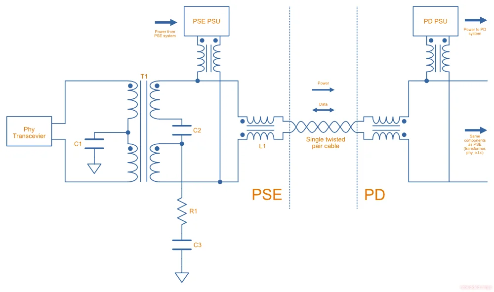
This is a placeholder for the reference: fig-spe-with-podl-diagram is a schematic showing the core component used to build a SPE with PoDL system.
Conventional IEEE 802.3 multipair Ethernet (including PoE) requires galvanic isolation from the chassis ground. According to IEEE 802.3bu (PoDL) and IEEE 802.3cg (SPoE) standards, PSE/PDs must provide at least 1 MΩ (@ 5 V ± 20%) isolation between all accessible external conductors and the interface (MDI).5
When PSE wants to provide power to a PD device, it first attempts to detect a PD device, and then classify it using a process called SCCP.10 The protocol also uses Cable Resistance Measurement (CRM) to assess the quality of the connection.5
For convenience, the standard allows the DC voltage to applied in either direction by the power sourcing equipment. This means that the receiver requires a rectifier (or similar) to support reverse polarity.10
This is a placeholder for the reference: tbl-podl-classes is a summary of the different PoDL classes defined in the IEEE standards and the various voltages, currents and powers supported by each class.
| Class | Standard | Class Type | V_PSE(max) (V) | V_PSE(min) (V) | I_PI(max) (mA) | P_PD(max) (W) | V_PD(min) (V) | Cable (AWG) | Cable length (m) |
|---|---|---|---|---|---|---|---|---|---|
| 0 | IEEE 802.3bu | 12V unregulated | 18 | 6 | 101 | 0.5 | 4.94 | - | - |
| 1 | IEEE 802.3bu | 12V unregulated | 18 | 6 | 227 | 1 | 4.41 | - | - |
| 2 | IEEE 802.3bu | 12V regulated | 18 | 14.4 | 249 | 3 | 12 | - | - |
| 3 | IEEE 802.3bu | 12V regulated | 18 | 14.4 | 471 | 5 | 10.6 | - | - |
| 4 | IEEE 802.3bu | 24V unregulated | 36 | 12 | 97 | 1 | 10.3 | - | - |
| 5 | IEEE 802.3bu | 24V unregulated | 36 | 12 | 339 | 3 | 8.86 | - | - |
| 6 | IEEE 802.3bu | 24V regulated | 36 | 26 | 215 | 5 | 23.3 | - | - |
| 7 | IEEE 802.3bu | 24V regulated | 36 | 26 | 461 | 10 | 21.7 | - | - |
| 8 | IEEE 802.3bu | 48V regulated | 60 | 48 | 735 | 30 | 40.8 | - | - |
| 9 | IEEE 802.3bu | 48V regulated | 60 | 48 | 1360 | 50 | 36.7 | - | - |
| 10 | IEEE 802.3cg | 24V | 30 | 20 | 92 | 1.23 | 14 | 18 | 1000 |
| 11 | IEEE 802.3cg | 24V | 30 | 20 | 240 | 3.2 | 14 | 14 | 1000 |
| 12 | IEEE 802.3cg | 24V | 30 | 20 | 632 | 8.3 | 14 | 24 | 1000 |
| 13 | IEEE 802.3cg | 55V | 58 | 50 | 231 | 7.7 | 35 | 18 | 1000 |
| 14 | IEEE 802.3cg | 55V | 58 | 50 | 600 | 20 | 35 | 14 | 1000 |
| 15 | IEEE 802.3cg | 55V | 58 | 50 | 1579 | 52 | 35 | 24 | 300 |
Class 15 provides the highest power output at 52 W.
PoDL Detection Phase
The detection phase is when the PSE tried to detect a PD device. The PSE sources a constant current between 9 and 16 mA with an open-loop voltage of 4.75 and 5.5 V. The PSE measures the voltage across the cable. If it is between 4.05 and 4.7 V the PSE concludes that a valid PD device is present.11
PoDL Classification Phase
Classification is done after detection and is when the PSE classifies the PD device into a specific class. This is done using a simple low speed one-wire protocol called SCCP. It is a pull-up, drive low protocol similar to I2C but with just the one wire. PSE provides the pull-up via a current source. Both the PSE and the PD can drive the line low by switching a transistor to ground.
Every SCCP transaction begins with the PSE driving the line low. If the PSE is transmitting, it drives it low to a set period of time. Different low durations determine whether a 0 or a 1 is sent. If the PD is transmitting, the PSE still drives the line low initially but then the PD takes over and holds it low for a set duration to determine a 0 or 1. Each bit is defined to take within 2.7 and 3.3 ms. If we assume the average of 3 ms, this makes the bandwidth a rather slow 333 bps. This is slow enough for MCUs to directly implement in firmware (i.e. no dedicated hardware peripheral required).11
Example ICs
DP83TC Family
The Texas Instruments DP83TC is a family of ethernet PHY ICs.
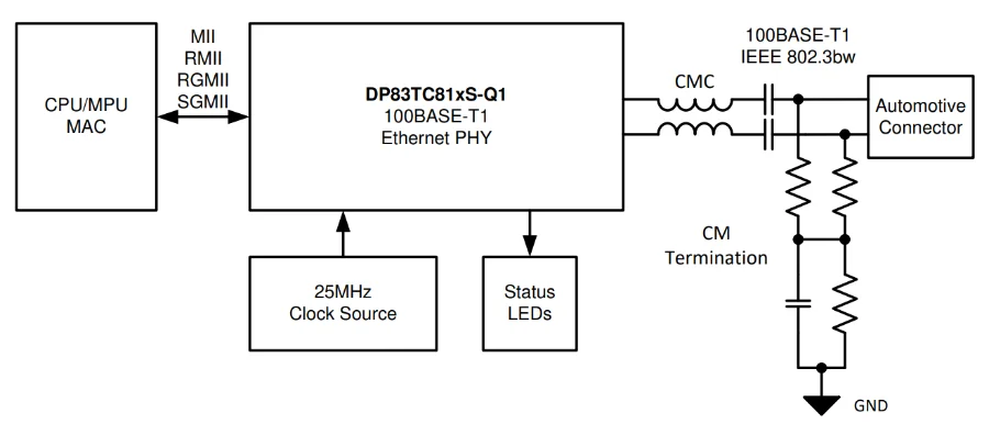
For example, the DP83TC813S-Q1 is a 100BASE-T1 PHY in a VQFN-28 package. It supports either MII, RGMII, RMII, or SGMII interfaces with the host MCU. This is a placeholder for the reference: fig-ti-dp83tc813s-q1-100base-t1-phy-simplified-application-schematic shows a simplified application schematic for the DP83TC813S-Q1.
Conversion Modules
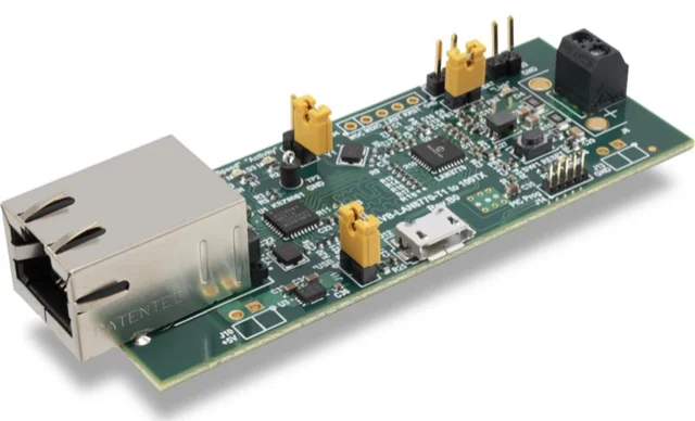
The Microchip EV02N47A is a conversion module which converts 100BASE-TX (standard ethernet) to 100BASE-T1 (single pair ethernet). It provides a conventional RJ45 jack for the 100BASE-TX side and a 2 port terminal block for the 100BASE-T1 side. The 100BASE-T1 is driven by an onboard LAN8770M transceiver.
A block diagram showing the high-level architecture of the Microchip EV02N47A LAN8770M converter board is shown below. The two Ethernet transceivers are connected via MII.
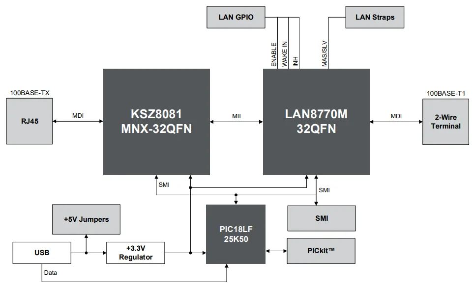
No configuration is required for the converter board to pass traffic through the two interfaces at 100 Mbps. However, a configuration tool is provided to set LAN8770M registers if custom configuration is required. The software talks via serial to the on-board PIC microcontroller that enumerates as a CDC class serial port.6
EtherCAT
EtherCAT is a communication protocol with its physical layer following the Ethernet standard in IEEE 802.3 (the magnetics and PHY are the same). However, the similarity somewhat stops there, it uses a novel technique where:
- Each device is daisy chained to the next via Ethernet cable.
- The master emits a Ethernet frame (telegram).
- Each slave device reads the data addressed to it “on the fly”, and inserts its own data into the frame “on the fly”.
- Propagation times between slaves are only limited by hardware propagation delays.
The master node can be implemented using any device with standard Ethernet capability, the same magnetics, PHY and MAC is used. However, whilst the slave node use the same magnetics and PHY, the MAC is replaced by a special EtherCAT Slave Controller (ESC) which can process frames on the fly.
lwIP
lwIP is a BSD-licensed implementation of the TCP/IP protocol suite with a focus on small resource (RAM and flash memory) usage. It is designed for embedded systems, and requires only 10’s of kB of free RAM and 40kB’s of ROM (e.g. flash)14.
It has support for IP, IPv6, UDP, TCP, ARP, PPPoE and more14.
Popular Chips
WIZnet W5xxx Family
The WIZnet W5xxx family of serial-to-ethernet ICs is very popular in the maker community. This family of ICs is used by the Arduino Ethernet board and the Arduino Ethernet Shield.
- W5200: This chip implements the PHY, the TCP/IP stack (fully hardwired), and the 10/100 MAC Ethernet MAC, in a QFN-48 package. It uses the SPI Protocol to talk to a microcontroller. It’s power save features include power-down mode and WOL (wake on LAN). It runs of 3.3V but has 5V I/O tolerance.
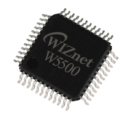
- W5500: Supports up to 8 independent sockets (i.e. 8 different connections to different ports). Contains a 10BaseT/100BaseTX PHY. Like the W5200 is runs of 3.3V but has 5V I/O tolerance.
Microchip LAN867x Family
Microchip’s LAN8670, LAN8671 and LAN8672 are ethernet PHY ICs that use 10BASE-T1S, allowing a multi-drop architecture of “at least 8 nodes and a minimum 25m of length”.
Footnotes
-
Wikipedia (2026, Mar 16). Ethernet [wiki]. Retrieved 2026-04-09, from https://en.wikipedia.org/wiki/Ethernet. ↩
-
Matthew Millman (2012). Cabletron 10BASE5 Ethernet transceiver with AMP vampire tap. University of Helsinki. Retrieved 2026-04-09, from https://www.cs.helsinki.fi/u/kutvonen/index_files/ethernet.html. ↩
-
Wikipedia (2025, May 11). Baseband [wiki]. Retrieved 2025-10-29, from https://en.wikipedia.org/wiki/Baseband. ↩
-
Donovan Porter (2018, Apr). 100BASE-T1 Ethernet: the evolution of automotive networking. Texas Instruments. Retrieved 2025-11-05, from https://www.ti.com/lit/wp/szzy009/szzy009.pdf. ↩ ↩2
-
Wurth Elektronik. Reference Design RD041 - Design of a Single Pair Ethernet System with Power over Data Lines (SPoE). Retrieved 2025-10-28, from https://www.we-online.com/files/pdf1/rd041b_design-of-a-single-pair-ethernet-system-with-power-over-data-lines-spoe-v1.pdf. ↩ ↩2 ↩3 ↩4 ↩5 ↩6
-
Microchip. EVB-LAN8770M_MC - Evaluation Board User’s Guide [datasheet]. Retrieved 2026-04-09, from https://ww1.microchip.com/downloads/en/DeviceDoc/EVB-LAN8770M-MC-Eval-Board-User-Guide-50002979A.pdf. ↩ ↩2 ↩3
-
Teledyne LeCroy (2020, Jul 30). Fundamentals of 100Base-T1 Ethernet [application note]. Retrieved 2026-04-21, from https://www.teledynelecroy.com/doc/100base-t1-ethernet-appnote. ↩ ↩2 ↩3
-
Vector (2023-03-21). Difference between Automotive and Standard Ethernet Technologies [KnowledgeBase article]. Retrieved 2025-11-02, from https://support.vector.com/kb?id=kb_article_view&sysparm_article=KB0013990&sys_kb_id=97ff00263b67eed0c1dc1d24c3e45aff&spa=1. ↩
-
Wikipedia (2025, Oct 25). Power over Ethernet [wiki]. Retrieved 2025-10-29, from https://en.wikipedia.org/wiki/Power_over_Ethernet. ↩ ↩2
-
Electric UI. A deep dive into Single Pair Ethernet. Retrieved 2025-10-28, from https://electricui.com/blog/spe-sensor-node. ↩ ↩2
-
Steffen Graf (2021, Nov). How to Implement an IEEE 802.3cg or 802.3bu Compliant PoDL PSE. Texas Instruments. Retrieved 2025-10-29, from https://www.ti.com/lit/ab/snla395/snla395.pdf. ↩ ↩2
-
Texas Instruments (2022, May). SNLS676 - DP83TC813x-Q1 TC-10 Compliant Small Form Factor 100BASE-T1 Automotive Ethernet PHY [datasheet]. Retrieved 2025-11-05, from https://www.ti.com/lit/ds/symlink/dp83tc813s-q1.pdf. ↩
-
Microchip. Microchip Technology EV02N47A [product page]. DigiKey. Retrieved 2026-04-09, from https://www.digikey.co.nz/en/products/detail/microchip-technology/EV02N47A/13175052. ↩
-
lwIP. Homepage. Retrieved 2024-08-13, from https://savannah.nongnu.org/projects/lwip/. ↩ ↩2