RS-232 Protocol

RS-232 is a digital data transmission protocol with origins dating back to the 1960’s. It was designed as a communication protocol to talk between DTE (data terminal equipment) and DCE (data communication equipment). It is closely related to the UART communication protocol provided by most microcontrollers, except that RS-232 uses higher-voltage signalling whilst UART is restricted between VCC of the microcontroller and GND.
| Property | Value |
|---|---|
| Drive Type | Single-ended |
| Num. Wires (excl. GND) | 2 (TX/RX) or 4 (TX/RX and RTS/CTS) |
| Duplexity | Full |
| Connection Topology | Point-to-point |
| OSI Layers | Layers 1 (physical) and 2 (data link) |
RS-232 is commonly used today for a variety of different purposes in embedded systems, incl industrial equipment, test and measurement equipment. RS-232 ports are no longer available on most desktop computers (and certainly not on laptops), but USB-to-RS232 adapters are cheap, popular and easy to use with almost any operating system. Microcontroller UART peripherals are commonly connected to a UART-to-RS232 converter to send data that is going off-board.
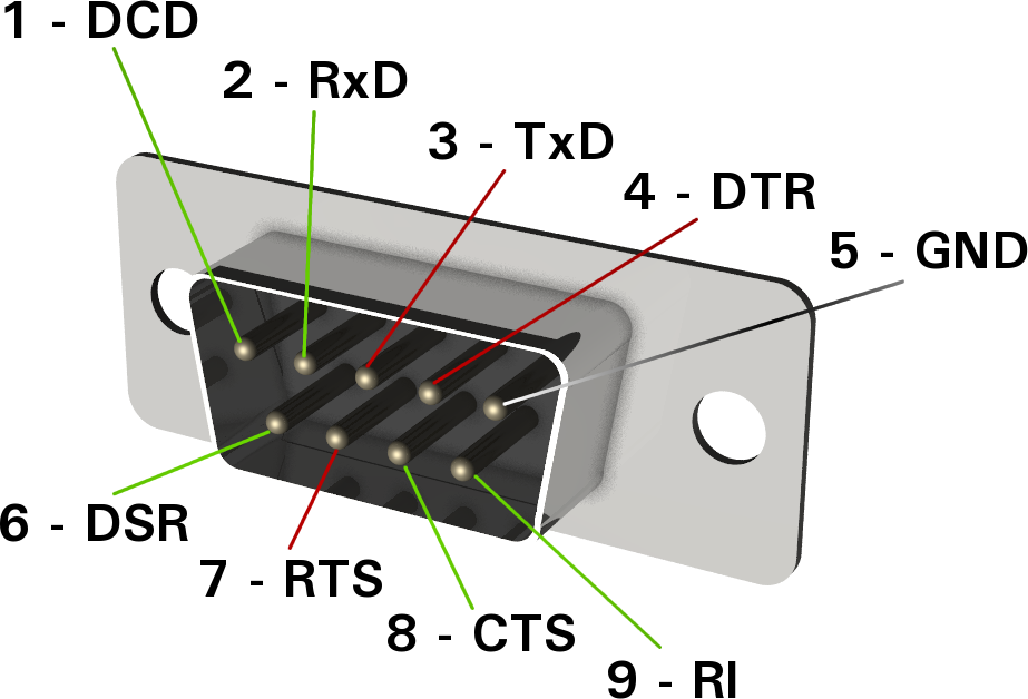
Pinout
Revisions
- RS-232C (or just shortened to RS-232)
- EIA-232-D (1987)
- EIA/TIA-232-E (1991)
DTE vs DCE
The RS-232 standard defines two types of devices:
- DTE (Data Terminal Equipment): Originally the “terminal” which the user interacted with. It displayed data to the user and accepted keyboard input.
- DCE (Data Communication Equipment): Originally the “modem” which connected to the telephone line. It sent and received data to and from the telephone line.
DTE and DCEs are not used today in this sense, but it is important to understand the distinction between them because it helps you understand the signals of the RS-232 protocol.
Rule-of-thumb: Most RS-232 serial interfaces with a male 9 or 25 pin connector are DTE’s, most with a female 9 or 25 pin connector are DCE’s.
Most often, manufacturers label the UART pins as DTEs. In this case, you have to swap all connections with their matching line. So TxD of device 1 is connected to RxD of device 2, RxD of device 1 is connected to TxD of device 2, RTS of device 1 is connected to CTS of device 2, etc.
Control Lines and Flow Control
Aside from the data lines, RS-232 also specifies a number of control lines. These days the original use of these control lines between DTE and DCE is all but gone, but they are still used (rather occasionally) for flow control and other basic signalling.
The following tables lists all of the flow control signals (as well as the data signals). The direction is specified from the perspective of the DTE (data terminal equipment). Matching signals are grouped together.
| Signal | Direction | Description | DB-25 Pin | DE-9 Pin |
|---|---|---|---|---|
| DTR (Data Terminal Ready) | DTE -> DCE | DTE drives this to indicate to the DCE that it is present. | 5 | 4 |
| DCD (Data Carrier Detect) | DCE -> DTE | DCE drives this when it is connected to the telephone line. | 8 | 1 |
| RI (Ring Indicator) | DCE -> DTE | The DCE drives this when it has detected a phone call. Note that there is no matching signal going the other way. | 22 | 9 |
| RTS (Request To Send) | DTE -> DCE | DTE drives this to tell the DCE to get ready to receive data. | 4 | 7 |
| CTS (Clear To Send) | DCE -> DTE | Driven by the DCE when it is ready to accept data. | 5 | 8 |
| TxD (Data Transmit) | DTE -> DCE | The DTE sends data to the DCE over this line. | 2 | 3 |
| RxD (Data Receive) | DCE -> DTE | The DCE sends data to the DTE over this line. | 3 | 2 |
| Common Ground (GND) | n/a | The common ground for all signals. | 7 | 5 |
| Protective Ground (PG) | n/a | The protective ground. This is usually just connected up to the common ground on the PCB. | 1 | n/a |
The flow control is a way of detecting when the receiver or transmitter is ready to accept or send new data. The UART protocol provides a few (all optional) methods for flow control:
- Hardware RTS/CTS lines
- Software XON/XOFF flow control
RTS/CTS
The RTS (Request to Send) and CTS (Clear to Send) signals were originally defined in the RS-232 standard to use with half-duplex modem (one direction at a time) such as the Bell 202. Note that half-duplex refers to the communication between the two DCEs (modems), not between the DTE and DCE (which is always full-duplex because of the TX and RX lines). The DTE asserts the RTS signal when it wants to transmit to the DCE. The DCE (modem) then does some handshaking with the modem on the other end, and once ready, asserts the CTS back to the DTE to grant permission to send data. It is important to realise that this flow control was only for data from the DTE to DCE. There was no similar mechanism in the original spec. to halt the flow of data from the DCE to the DTE.1
In the 1980s modems were increasingly full duplex and there was no need for the original RTS/CTS spec. At this point, they began to be repurposed so that the RTS indicated when the DTE was ready to receive data from the DCE. This was described in the RS-232-E/TIA-232-E standard, which defined a new signal called RTR (Ready to Receive). This used the same pin as RTS (and in doing so, essentially changed the functionality of RTS).1
The use of RTS to signal when the DTE was ready to receive data from the DTE and CLS to do the same but in the opposite direction meant the two signals were now independent of one another and can be considered proper hardware “flow control”. Typically, a microcontroller may have one or two UART peripherals that support this feature, while the rest are just basic non-flow control UARTs.
A small amount of power can be extracted from the RTS and CTS lines for powering low-power devices.
Transmission Distances
15m or less
Higher-Level Protocols
Do you need a higher-level communication protocol that works over a UART connection? See the SerialFiller library on GitHub (written in C++). SerialFiller uses a publish/subscribe mechanism and works well on point-to-point serial connections such as UART.
Interfaces
The pinout of a typical Analog Devices RS-232 to UART transceiver is shown below.
Another example of a RS-232 to CMOS UART converter is the MAX3221IDBE4. It supports an auto-shutdown feature based on the voltage-level of the receiving RS-232 line.
Driver ICs
MAX3227
The Maxim MAX3227 is a popular RS-232 line transceiver. It contains 1 driver and 1 receiver as is designed to be driven from CMOS signals (e.g. connected to a microcontroller UART)2. Texas Instruments produces a drop-in replacement part for the MAX3227, the MAX3227CDBR (the CDBR standing for commercial temp. range, tape and reeled).3
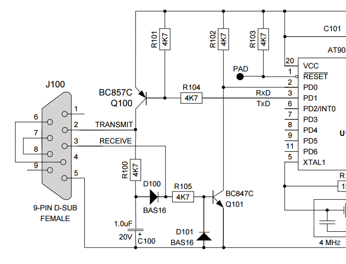
Cheap Discrete-Part RS-232 To TTL Converter
A RS-232 to TTL logic-level converter can be made out of a few discrete components. The schematic shown below uses some clever circuitry, including a charge-pump like circuit, to generate the negative voltage required for RS-232 transmission back to the computer.
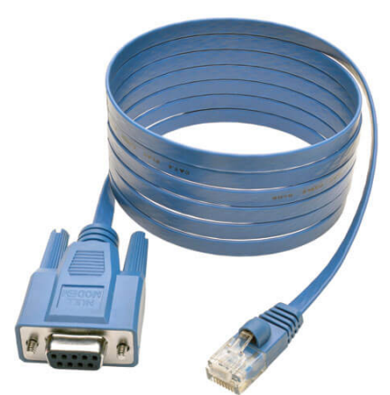
RS-232 DE-9 To RJ-45 Cables
Many routers contain a RJ-45 socket that carry a RS-232 bus. They are designed so you can plug in a DE-9 to RJ-45 cable and connect the router to a PC for configuration. One example of a cable is the Tripp Lite RJ45 to DB9F Cisco Serial Console Port Rollover Cable, as shown in the below image:
The common pinout for this cable is shown in the table below5 6:
| RJ-45 | Signal | DB-9 | Signal |
|---|---|---|---|
| 1 | RTS | 8 | CTS |
| 2 | DTR | 6 | DSR |
| 3 | TxD | 2 | RxD |
| 4 | GND | 5 | GND |
| 6 | RxD | 3 | TxD |
| 7 | DSR | 4 | DTR |
| 8 | CTS | 7 | RTS |
Bluetooth
Bluetooth devices can support RS-232 emulation over Bluetooth. There is an official standard in Bluetooth Classic, and many proprietary implementations in Bluetooth Low Energy (BLE). See the Serial Ports over Bluetooth for more information.
Footnotes
-
Wikipedia (2025, Aug 20). RS-232. Retrieved 2025-08-26, from https://en.wikipedia.org/wiki/RS-232. ↩ ↩2
-
Maxim (2011, Feb). MAX3224–MAX3227/MAX3244/MAX3245: 1µA Supply Current, 1Mbps, 3.0V to 5.5V, RS-232 Transceivers with AutoShutdown Plus (datasheet). Retrieved 2022-03-02, from https://datasheets.maximintegrated.com/en/ds/MAX3224-MAX3245.pdf. ↩
-
Texas Instruments (2006, Feb). AX3227: 3V to 5.5V Single-channel RS-232 Line Driver/Receiver With ±15kV ESD Protection (datasheet). Retrieved 2022-03-02, from https://www.ti.com/lit/ds/symlink/max3227.pdf. ↩
-
Tripp Lite. RJ45 to DB9F Cisco Serial Console Port Rollover Cable, 6 ft. (1.83 m). Retrieved 2022-05-17, from https://assets.tripplite.com/product-pdfs/en/p430006.pdf. ↩
-
Juniper (2021, Nov 13). MX2020 Universal Routing Platform Hardware Guide: RJ-45 to DB-9 Serial Port Adapter Pinout Information. Retrieved 2022-05-17, from https://www.juniper.net/documentation/us/en/hardware/mx2020/srx4600/topics/concept/port-rj45-db9-adapter-pinout.html. ↩
-
U.S. Converters LLC. Making a DB to RJ45 adapter. Retrieved 2022-05-17, from https://www.usconverters.com/downloads/support/db9_rj45_assembeling_guide.pdf. ↩