Connectors

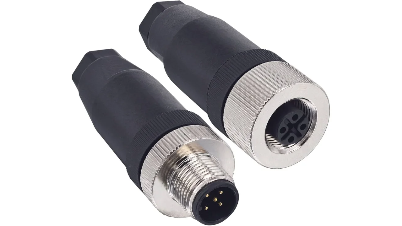
Electrical connectors are physical devices to electrically connect things together. Not only are they used in the traditional sense to connect a wire to a board (board usually means PCB), but there is a huge number of types to connect wires to wires, boards to boards, wires to panels (panel mount), breakouts, and more. There are specialty connectors for RF (radio frequency), high current and high voltage. Connectors can also be characterized by their shape, for example the popular M8/M12 circular connectors.
This page will hopefully explain the various types of connectors you can purchase and when they should be used in electronic/embedded projects.
Child Pages


Connector Manufacturers
| Name | Website | Range | Provide 3D Models | Affordability (1 expensive, 10 cheap) | Site Usability (1 bad, 10 good) |
|---|---|---|---|---|---|
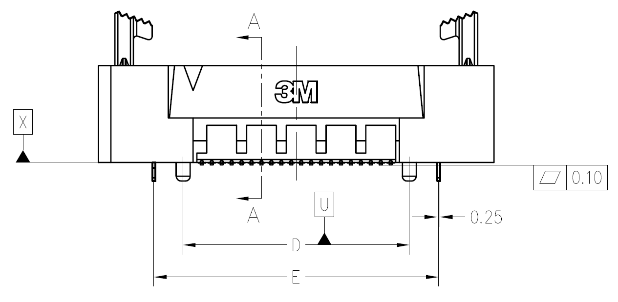
| 3M | http://www.3m.com/ | Card edge (inc. latching) | Yes, but not always for all parts in a connector family. (Step, IGES, Parasolid) | 3 | |
| Harting | http://www.harting.com | Card edge | Yes (Step) | 5 | |
| Hirose | http://www.hirose.com/ | High-end circular | Yes, after providing your paid-for email address. (Step) | 5 | |
| Molex | http://www.molex.com | Headers Wire-to-Board Card edge | Yes (Step) | 3 | 6 |
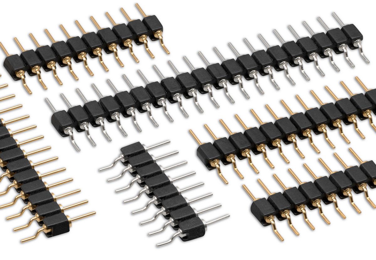
| Samtec | http://www.samtec.com | Backplane Headers (various pitches, and both square-post and machined) Rugged circular. | Yes (Step) | 7 | 8 |
| TE Connectivity | http://www.te.com | Backplane | ? | 6 |
Tin vs. Gold Plating
Many connectors come to at least two plating options, either tin or gold. Gold is a more expensive option, but offers a lower initial contact resistance, lower corrosion over time, and lower mating force (which may or may not be a good thing).
There is the 50:50:50 rule (taken from www.connector.com, as of Dec 2017, link no longer alive) when it comes to deciding which plating to choose. The rule says that tin is the best choice if:
- You have less than 50 contacts (due to the mating force getting too large)
- The connector will experience 50 or less mating cycles
- You can live with 50mOhms of contact resistance over time
Selecting gold tinned contacts can add a good US$0.50 or more to the price of the connector.
Mixing the two plating metals is not recommended! The corrosion rate is greatly increased when two dissimilar metals come into contact with each other (this is due to the difference in the metal’s electrode potentials, which is +1.5V for gold, and only +0.15V for tin).
Telecom Connectors
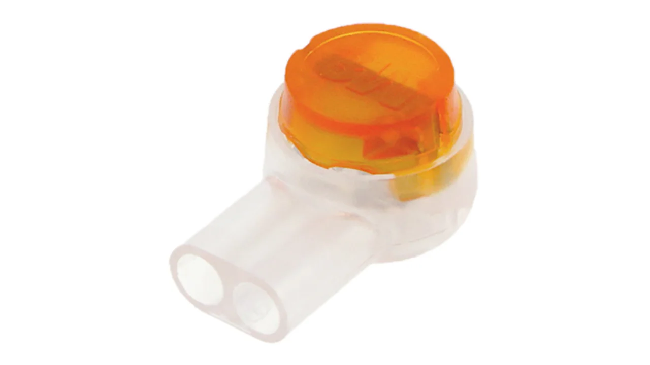
BT Connector
The connector called the “BT” connector (which is an acronym for the British Telecom connector) is commonly used through out houses in many countries (including the U.K. and New Zealand) to plug into a Telecom jack that is mounted on the wall. It’s proper name is the BS6312 431A plug. You can get cheap BT to RJ-11 adapters.
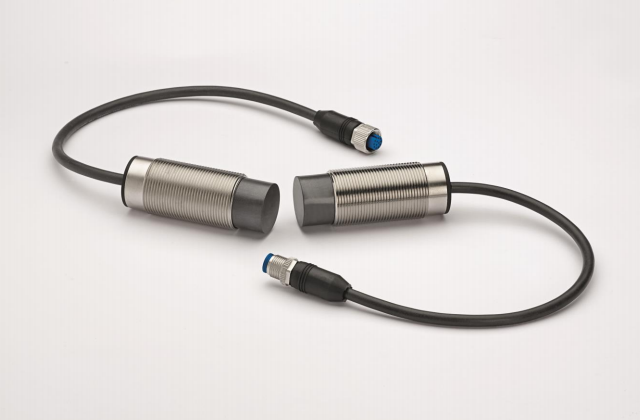
Contactless Connectors
Contactless connectors is the name given to connectors which don’t require a physical electrical contact between the two mating pieces (they still may require physical mechanical contact). They can transmit both signals and power from one side to the other. This is normally done through magnetic/capacitive coupling.
This is still a relatively new field compared to other forms of connectors, and unit prices are still very high.
TE Connectivity make a range under the family name ARISO. They are capable to transmitting up to 12W of power at 24VDC.
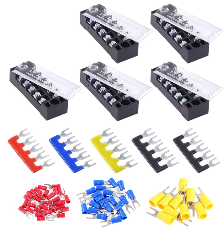
Barrier Strips
Barrier strips (a.k.a. barrier blocks) are rows of screw-based electrical clamps designed to connect wires together. They are very similar to [^_terminal_blocks, terminal blocks], however they generally provide better protection than terminal blocks against loose of frayed wire ends shorting out against adjacent positions. They are also generally rated for higher current/voltage applications than terminal blocks (300-600V, 10-30A ratings are common), and consequentially usually larger (pitches of 8-12mm).
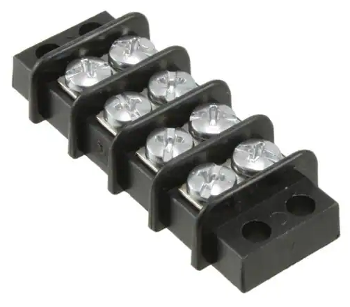
Whilst terminal blocks don’t usually have an exposed metal that can easily short out against neighbouring parts, barrier strips are open on the top face (to allow for the connection of lugs). If the exposed conductors are a problem, you can purchase some barrier strips that come with insulating covers. The covers are usually see-through and made of plastic.
Barrier strips can be found on DigiKey at https://www.digikey.com/en/products/filter/terminal-blocks-barrier-blocks/368.
Board-to-Board Connectors
Board-to-board connectors which connect to PCBs side-by-side are called coplanar connectors.
Board-to-board-connectors which connect PCBs ontop of one another are called mezzanine or stacked connectors.
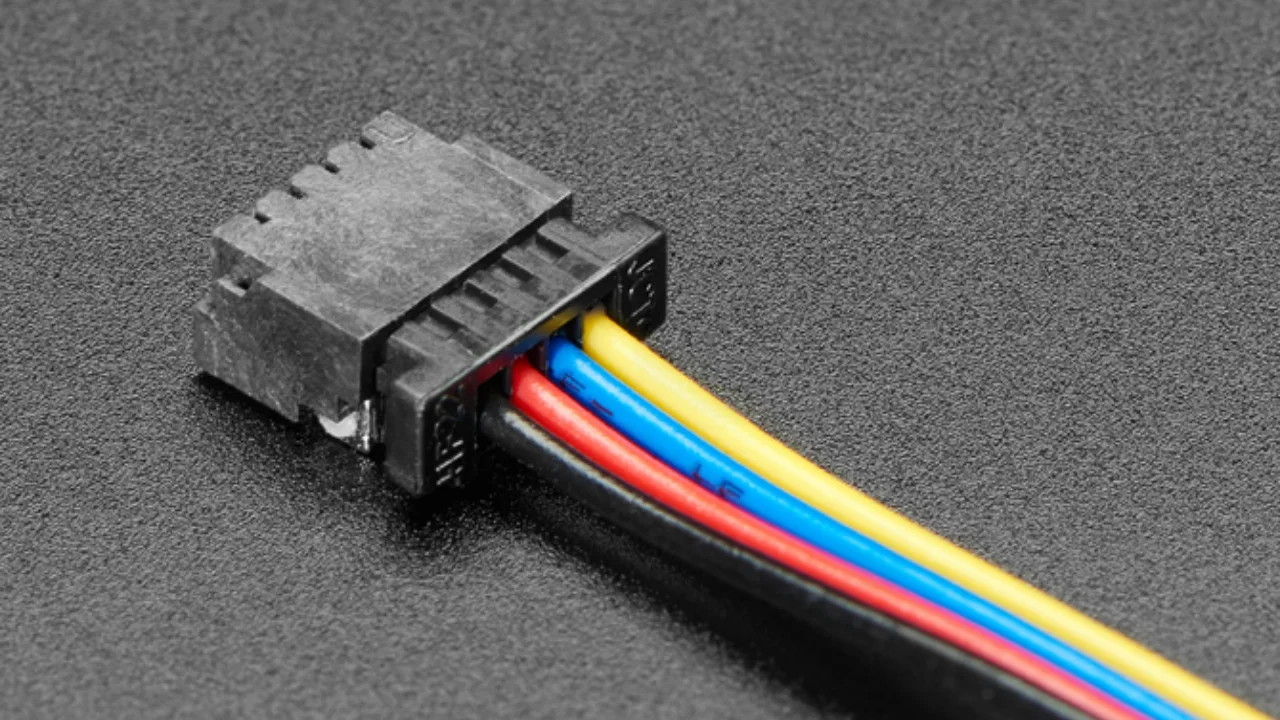
Wire-to-Board (WTB) Support
Some board-to-board connector families are have wire-to-board support, with a special wire-crimped inline receptacle which mates with the PCB-mounted connector that works with both the board-to-board and wire-to-board connectors.
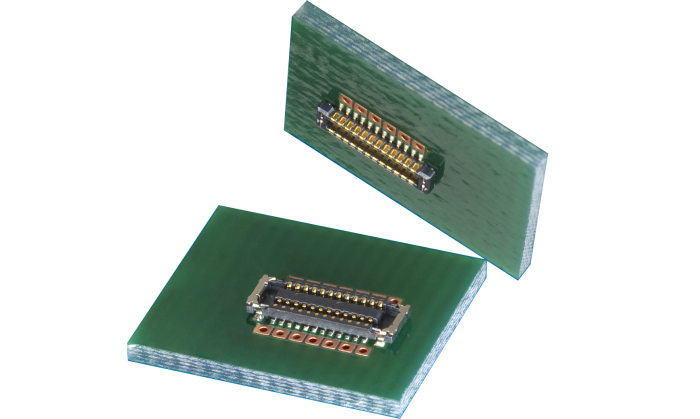
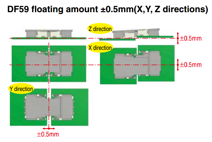
The Hirose DF-59 family is a set of board-to-board/board-to-wire connectors. The special feature about this family is the “floating” contact which allows up to 0.5mm of mis-alignment between the boards.
Mains Power Connectors
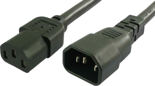
IEC 60320
The C13/C14 coupler is very common for powering computers, computer screens and other tech equipment from mains power. In New Zealand, they are commonly called “jug plugs”.
PCB Card Edge Connectors
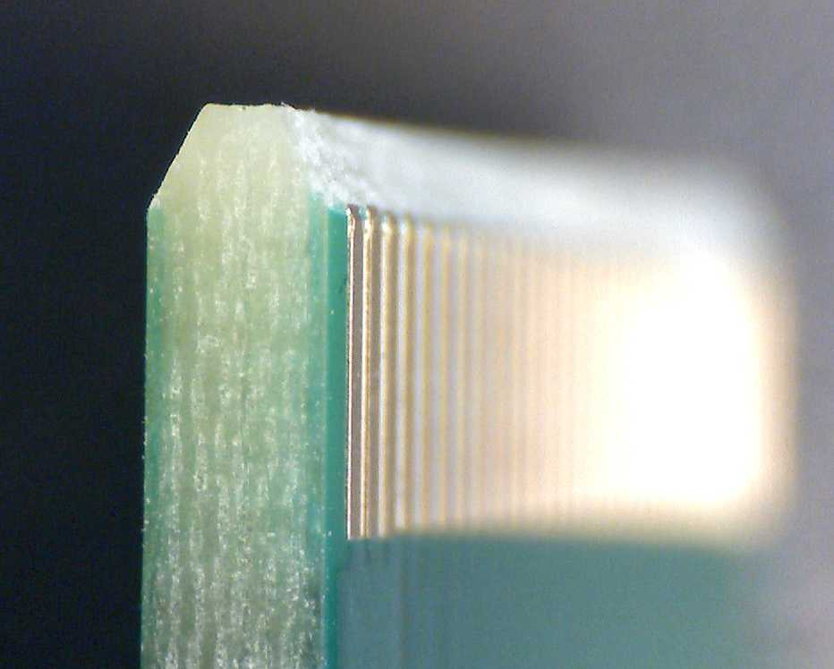
This is a cheap and many-pin capable solution when you want to connect two PCBs together. PCB card edge connector involve using the edge of one of the mating PCBs as the connector, by etching/routing “fingers” on the PCB. The other mating part of the connector is designed to accept these fingers. Most card edge connectors are used when the PCBs are at right-angles to each other, although you can get connectors designed for parallel and co-planar connections.
The fingers that are etched on the PCB are usually gold plated to make the contacts more reliable (the normal lead/tin coating oxidises too quickly). This is a special process that most PCB manufacturers will support, and does not add much to the cost of the PCB. The supported PCB thickness of most of these connectors is around 1.60mm (which is pretty standard). Also, it is recommended to add a small bevel to the inserted end of the PCB to facilitate mating. Again, most quality PCB manufacturers will support this.
Card-edge connectors are very susceptible to board warping and board thickness errors, so takes these into consideration when adding card-edge connectors to your PCB design.
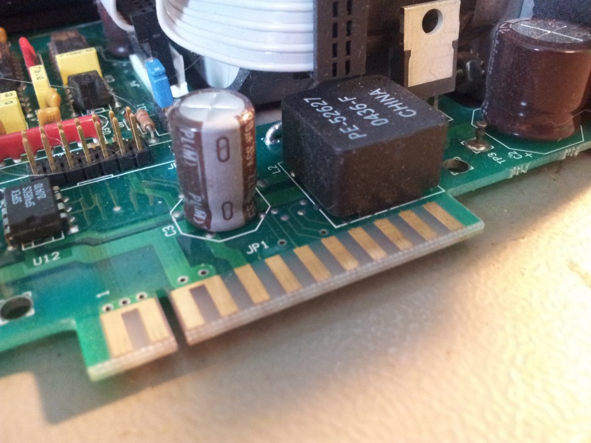
The following image is of PCB card edge connectors on the Cavro XL-3000 syringe pump.
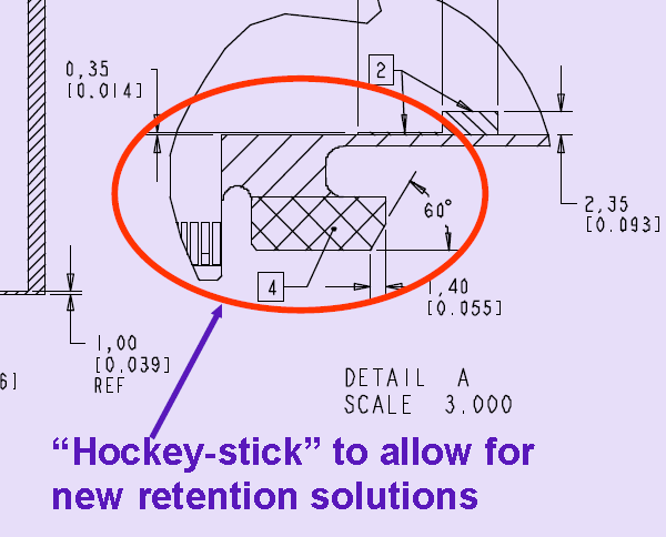
You can get PCB card edge connectors which have latches, which lock in the daughter board which has special “hockey stick” pieces routed on the sides.
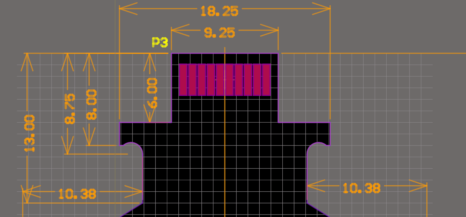
This is a screenshot from a PCB design for the male part of a card-edge connector in Altium.
This is a female latching card-edge connector.
In some rare cases (e.g. the Sullins EBC Card-Edge connector series), aside from the socket, the connector manufacturer will also manufacture a plug which replicates PCB fingers, instead of you using the PCB for this purpose.
Identifying Connectors
Unlike most other electrical components, most connector manufacturers do not append any letter codes in the part numbers for connectors, rather they are just a long sequence of numbers. This can make part recognition very confusing (e.g. when you see an IC with “74” in it’s part name, you instantly think of digital logic). A standard way to indicate pin 1 on a connector PCB footprint is to make the copper pad surrounding the pin 1 hole to be a different shape than the rest (e.g. square, while all the others are round).
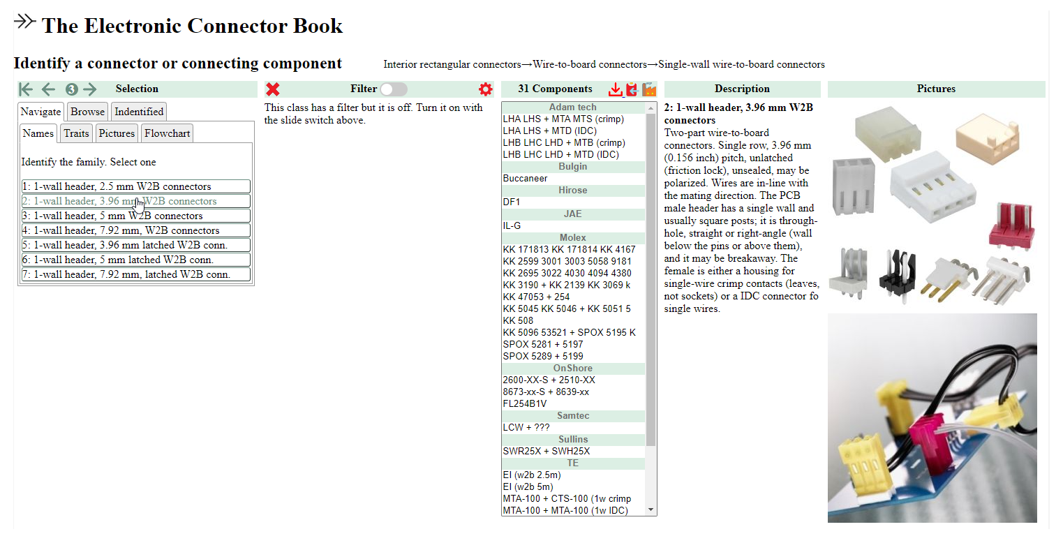
The website https://connectorbook.com/identification.html is a great tool to help you identify unknown connectors. If guides you through a series of questions which narrows down the connector you are looking at.
Footnotes
-
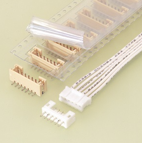
JST. PH connector. Retrieved 2021-12-03, from https://www.jst-mfg.com/product/detail_e.php?series=199. ↩
-
The Electronic Connector Book. Identify a connector or connecting component. Retrieved 2021-12-03, from https://connectorbook.com/identification.html. ↩