Luxcity UV Tonic Control System

- Project Start Date: 2012-09-27
- Project Completion: 2012-10-21
- Status: Complete
The Challenge
To design and build a sequencing control system for 64 solenoids that controls a mixture of UV tonic and air into a manifold of pipes to be pumped around a structure. This was for a team participating in the Luxcity Project (http://stajegrouparchitects.wordpress.com/), or news articles
- http://events.nzherald.co.nz/2012/luxcity/christchurch-city/christchurch)
- http://www.stuff.co.nz/the-press/news/7805643/City-to-take-shape-for-one-night
or the Luxcity event page itself (http://www.luxcity.co.nz/, as of Dec 2017, website dead)
or the Luxcity page on EventFinder (http://www.eventfinder.co.nz/2012/luxcity/christchurch-city/christchurch)

EDIT 2012-10-30:
Post-event there have been another news article:
Repository
The repo for this project can be found on BitBucket at https://bitbucket.org/gbmhunter/luxcity-tonic-uv-control-system. It contains the firmware and datasheets.
The Hardware
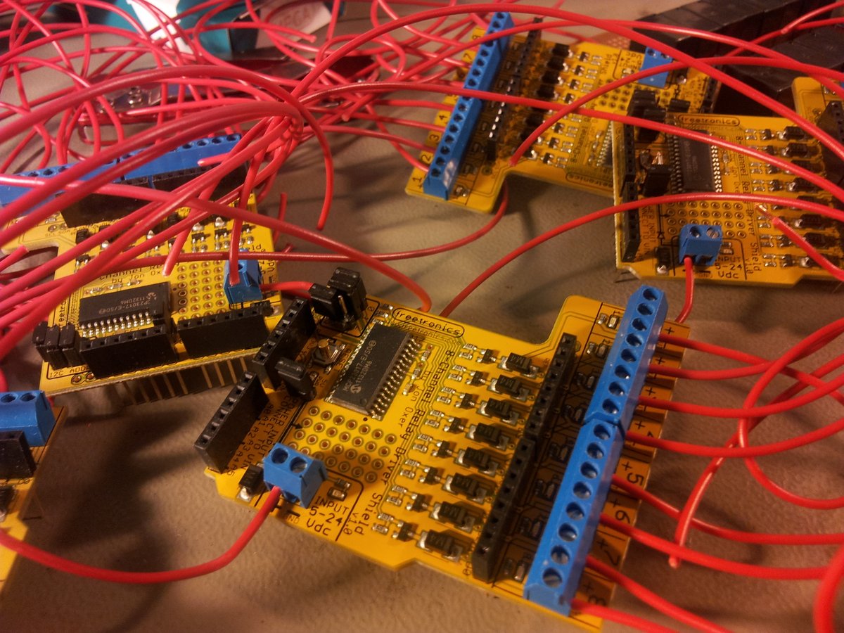
8x FreeTronics 8-Channel Relay Driver Shields
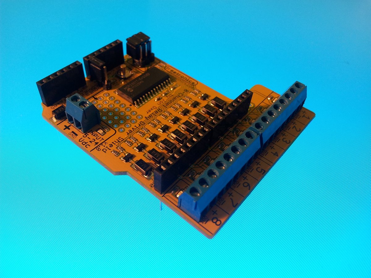
- Manufacturer: Freetronics
- Store URL: http://www.freetronics.com/products/relay8-8-channel-relay-driver-shield
- Datasheet: https://github.com/freetronics/RelayDriverShield8/blob/master/RelayDriverShield8.pdf
- Supplier: NiceGear
The I2C controlled shield provides 8 outputs that can drive standard relays. Being I2C controlled, it only uses 2-pins of the Ardunio. Luckily, the I2C address settings are 3-bit, meaning I could just control all 8 from a single I2C line. The boards feature the MCP23017 I2C expander IC (datasheet).

64x SPDT 12V Relays

- Manufacturer: Zhejiang Dongya Electric Co. Ltd.
- Supplier: NiceGear
- Supplier Link: http://nicegear.co.nz/components/relay-spdt-sealed/
- Datasheet: click here
- Rated Coil Load: 12V @ 37.5mA
- Coil Resistance: 320Ω
- Minimum Coil Load: 5V @ 10mA
- Operate Time: 20ms
- Release Time: 10ms
64 relays are needed to control the 62 tonic water/air solenoid valves (plus 2 spare). Since there was 64 of them, they needed to be cheap. These ones were brought for around NZ$3 each.
62x 12V Solenoid Valves
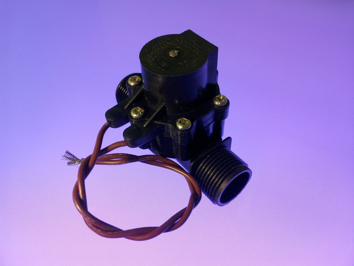
- Manufacturer: HR Products
- Supplier: HR Products
- Datasheet:
http://www.hrproducts.com.au/resources/Valves%20MV%20Series/MV80.pdf(as of Dec 2017, URL unavailable) - Operating Voltage: 12V
- Inrush Current: 320mA
- Holding Current: 260mA
- Power Consumption: 8W
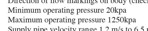
- Minimum Operating Pressure: 20kPA
- Maximum Operating Pressure: 1250kPA
62 solenoids are needed to either allow tonic or air to flow into one of the 31 pipes. When I first received them, I had a horrible feeling as I blew in one end and the solenoid let air through with some resistance. This was until I realised that they have a minimum operating pressure of 20kPA.
1x Arduino Uno
- Manufacturer: Arduino
- Supplier: NiceGear
- Supplier Link: (click here)
I decided to use the Arduino development environment for speed, simplicity, and pre-existing hardware/firmware. The USB cable was able to provide enough power to turn on all 64 relay lights and the LCD screen (including backlight), without causing an over-current fault.
2x Power Supplies
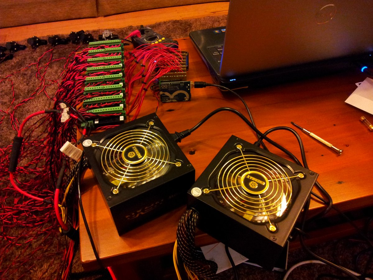
- Manufacturer: EnerMax
- Product: TomaHawk2 500W ATX2.2 PSU
- Supplier: MightyApe
- Product Page: click here
- Total Continuous Rated Power: 500W
- Output Voltages: 12Vx2, 5V, 3.3V, -12V
A PSU is needed to power the 64 relays and solenoids. This gave me a scare when I first received it, as it was ‘apparently’ not working. After some research I discovered that I needed to short out the green wire on the main connector to ground before the PSU would turn on.
They quote that there are two +12V supplies, but when using a multimeter, there was no resistance between any of the +12V wires, so either a) they are lying, or b) the two +12V outputs are connected together internally.
1x Arduino LCD Screen Shield
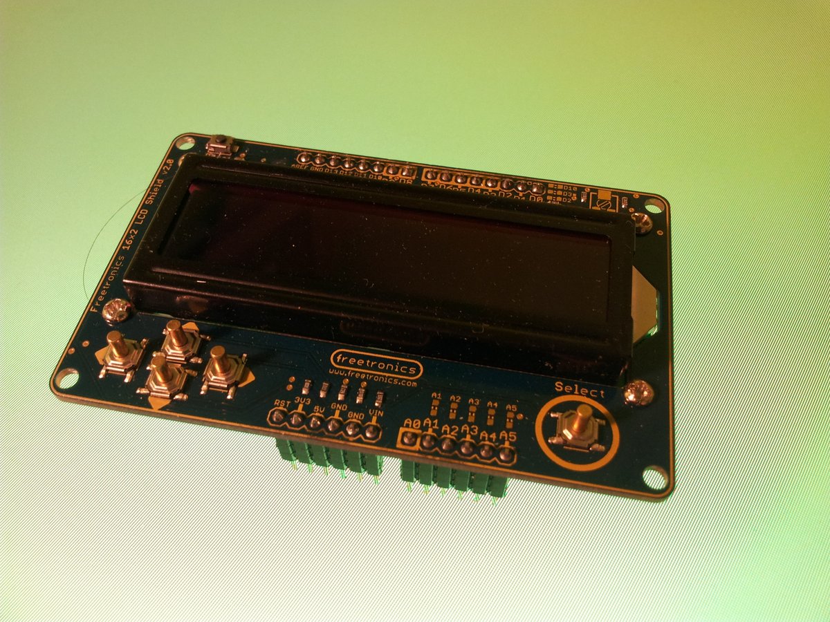
- Manufacturer: Freetronics
- Supplier: NiceGear
- Product Page: (click here)
It just so happened that the relay driver shields are mount-compatible with the LCD screen shield, as the driver shields only use analog pins 4 and 5 for I2C communication, and the LCD screen only uses digital I/O.
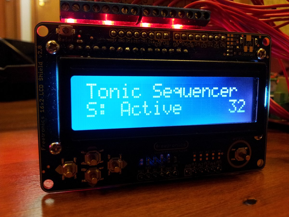
The LCD screen was one of easiest parts of this project to setup. Built in libraries for controlling an LCD are included in the Arduino IDE. It literally took about 5 minutes to get this working (see below).
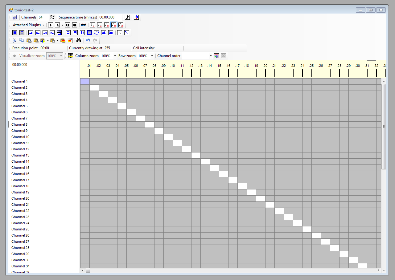
Vixen Software
- URL: http://www.vixenlights.com/
- License: Closed-source, free to use.
Vixen is a free PC-based sequencer designed for controlling lights. Although not open-source, it is very versatile, being built upon the .NET framework, and provides an API to build your own input/output plugins.
To get around the problem with Vixen not outputting cells with an intensity of 0 (the firmware can’t recognise what output value is for what channel unless all 64 are output in the correct order), I made the minimum allowable intensity equal to 1, so that Vixen outputs a value for every cell at every time step, and the firmware looks for a non-one value.
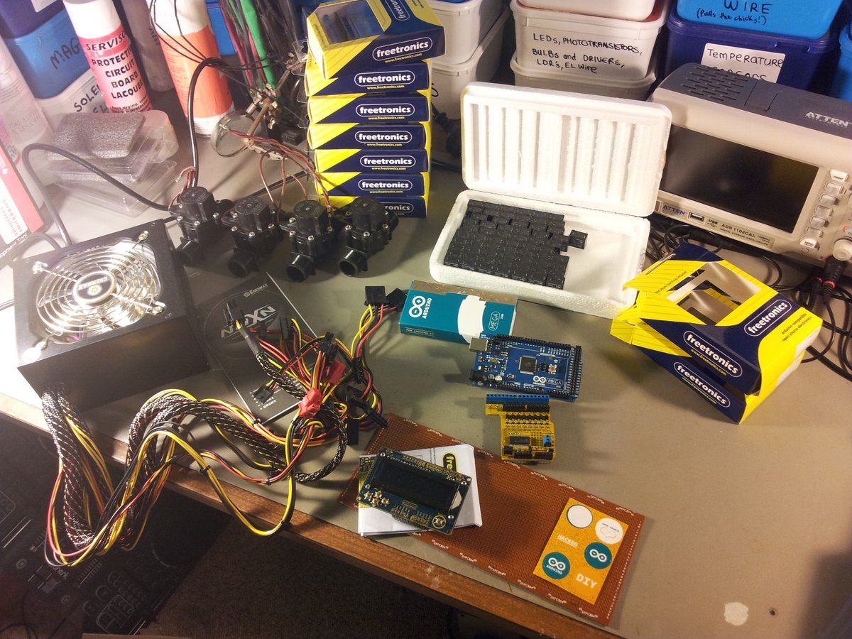
Construction
The hardware! (just after arrival).
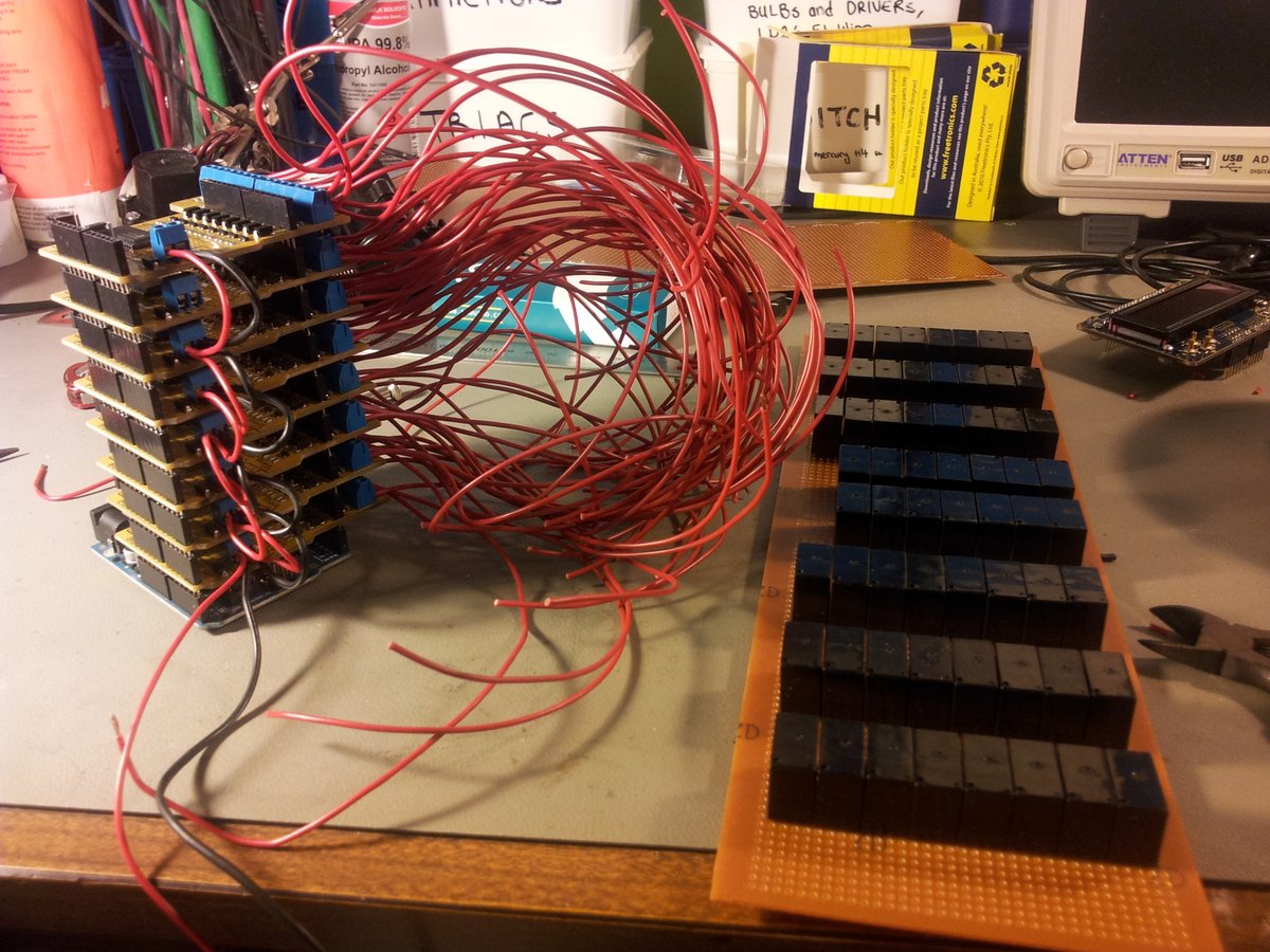
The relay boards and LCD were stacked ontop of each other.

Wiring up the relay boards.
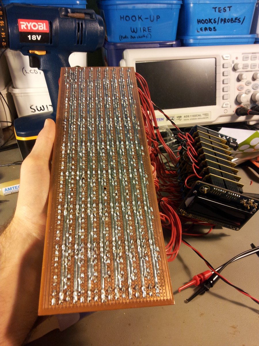
Placement of the relays onto strip board (they JUST managed to fit all on one board).
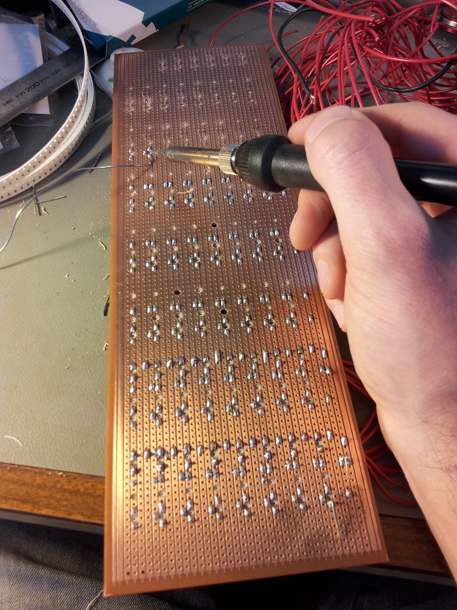
A quick way of breaking tracks on prototype board.

Soldering the relays, relay coil inputs, and power connectors to the board.
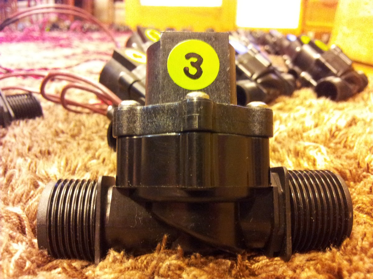
The 62 solenoid valves.
After testing a solenoid valve with the system, the comms between the computer and Arduino dropped out when the solenoid was turned off. I realised that although the relay shield boards had protection diodes, I still needed to add some to the solenoid’s (on the relay outputs), as this inductive kickback was coupling into the digital system. Luckily I had a string of 1N4003 diodes on hand…

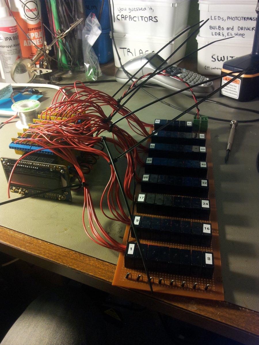
The Arduino, relay control boards, and the relay board, semi-assembled.
The bottom-side of the prototype board, fully soldered. Notice the heavy duty rails that deliver the power to the relays/solenoids. Even with these thick lines of solder, when half (31) of the solenoids where turned on, the board got considerably warm around the PSU entry point.
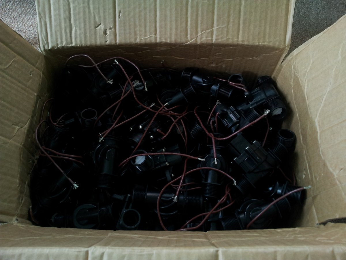
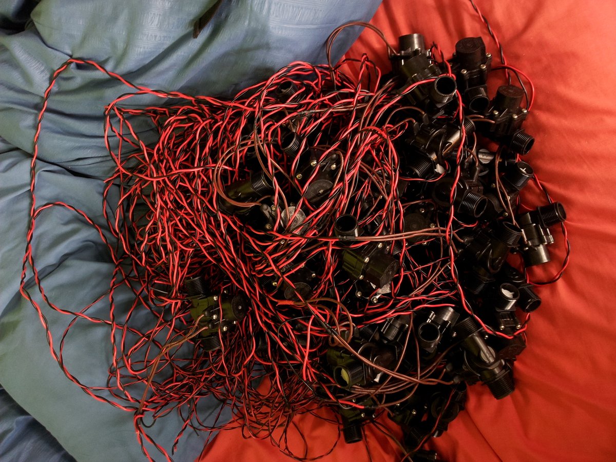
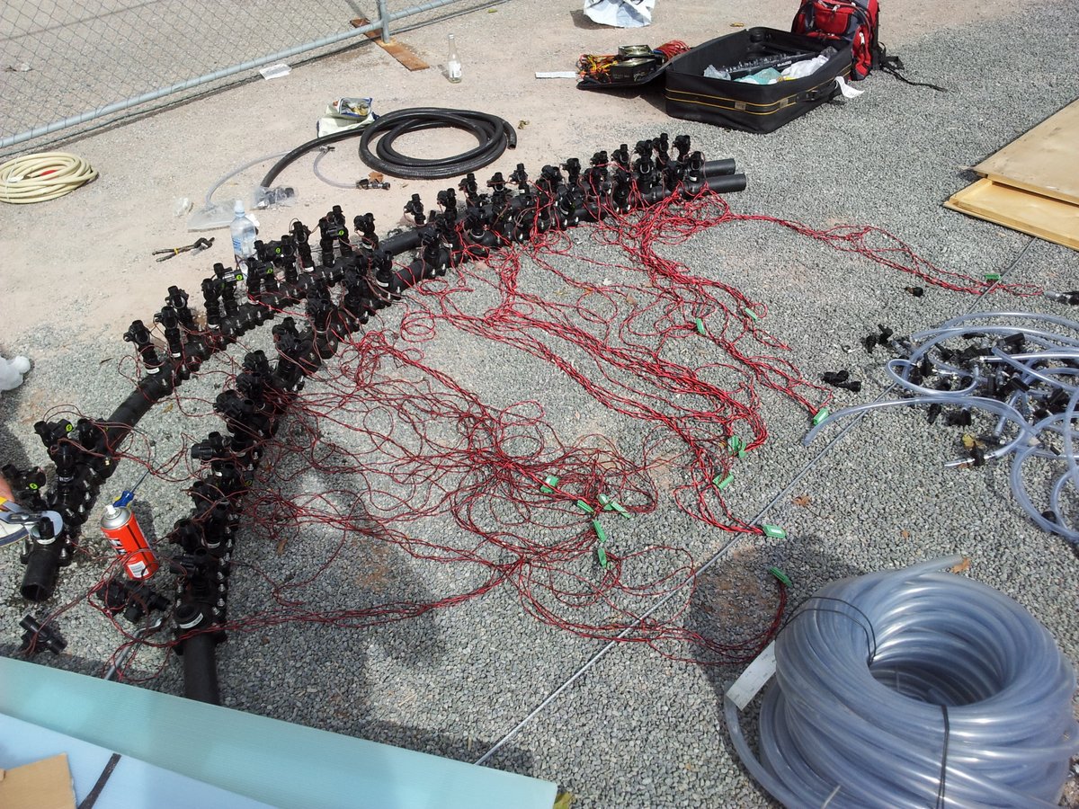
Wiring up the solenoids, as they need to have a 2m cable reach. I’m going through 100m cable rolls like it’s Christmas.
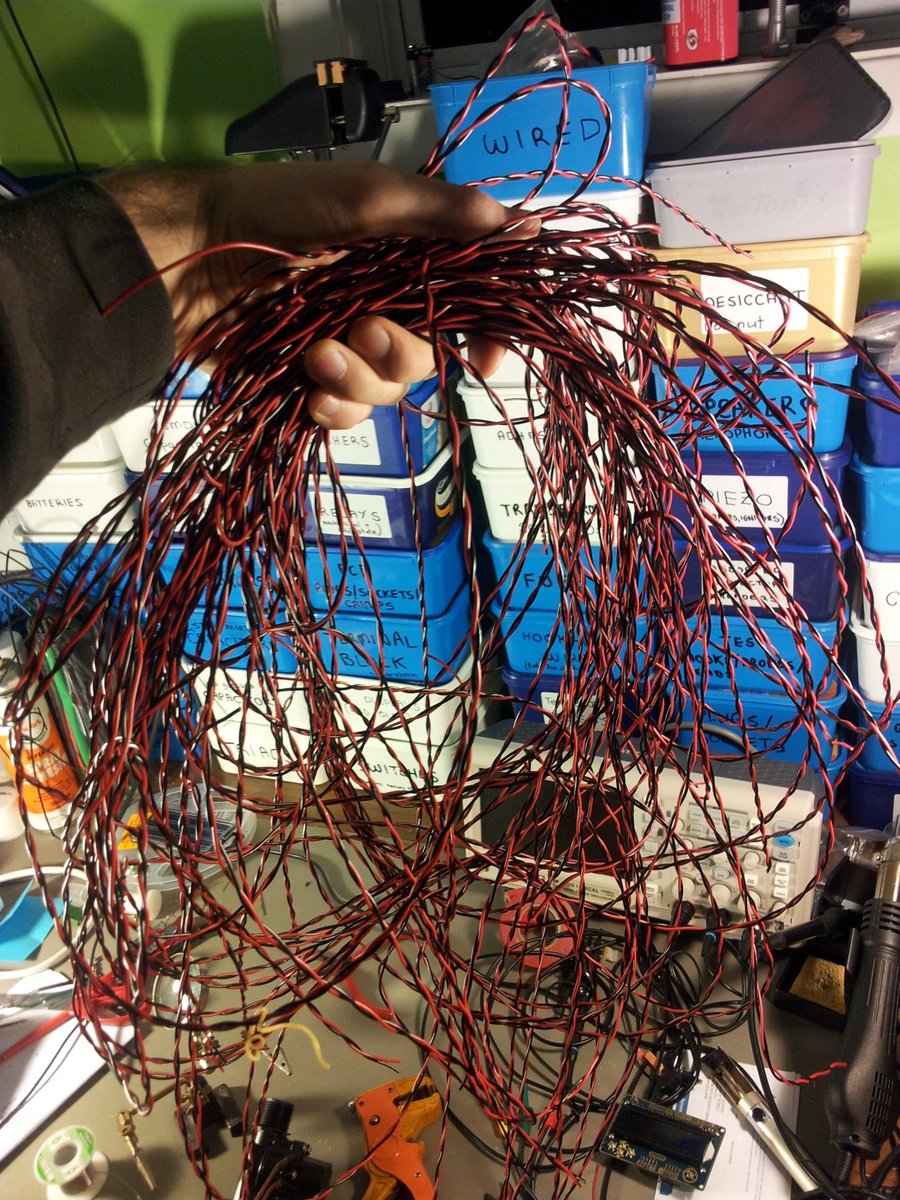
The pile of wired solenoids. It took a good 8+ hours to wire these up!
Shorting out the green wire to ground on the PSU to get it to turn on.

Adding small-valued power resistors in series with the PSU outputs to make them share the current equally.

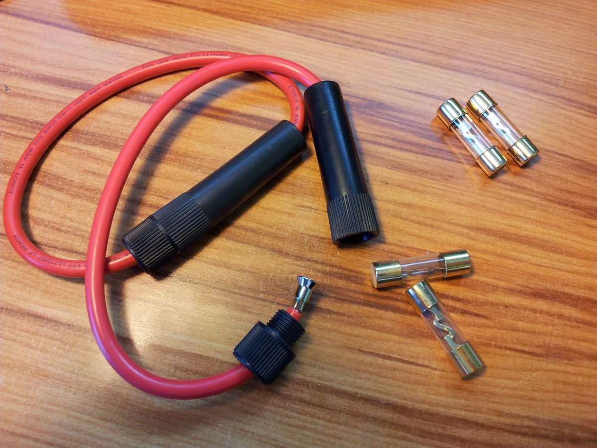
The heavy duty fuses used to protect the +12V rails of the power supply. The two in use are 30A 5AG fuses, and the two spares are 40A.
The LCD screen working. This part was a breeze, it was an Arduino capable LCD shield, and there was a pre-written library for the firmware. It literally took less than 5 minutes to get working.
The solenoids were numbered so sequencing would become confusing when out in the field.
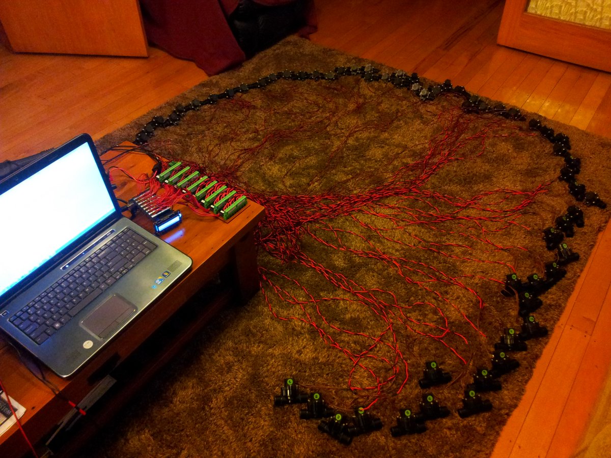
Testing the complete system the night before it’s due to be used.
The Vixen software sequence used to test the solenoids. Each solenoid is turned on for 1 second in sequential order.
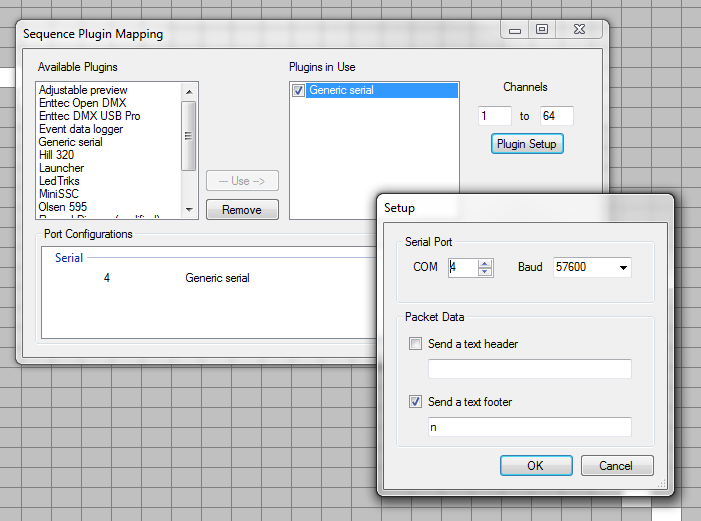
The settings to configure the ‘Generic Serial’ output plugin in Vixen.
Onsite
The manifold with the solenoids in place, being assembled on-site.
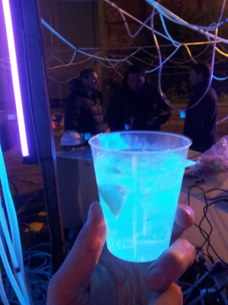
Carrying the water tank for the gin and tonic drinks down the road to the the construction site.

The tensioned cable structure being hoisted into the air by the crane.

The annoying street-light which dampened the fluorescent effect.
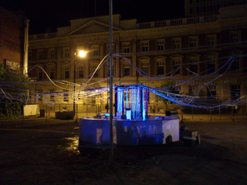
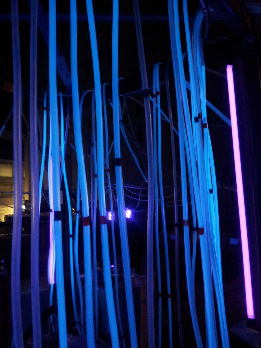
The pipes with tonic inside them, glowing with UV.
Gin and tonic!
Some of the other structures at the Luxcity event.


Firmware
I firstly considered DMX Control (as described in a FreakLabs tutorial at http://freaklabs.org/index.php/Tutorials/Software/Light-Sequencing-and-Decoding-DMX-with-an-Arduino.html, as of Dec 2017, URL unavailable), but this required hacking the Ardunio software platform (specifically, the HardwareSerial.cpp file) to get the UART to work correctly. I found it more elegant to use the Vixen output plugin ‘Generic Serial’ instead, as this worked without any hacking.
The firmware can be found in the project repo under ‘src’ on BitBucket at https://bitbucket.org/gbmhunter/luxcity-tonic-uv-control-system. Since there wasn’t much to it (one file of around 320 lines or so, I have also shown it below. Note that changes may of been made to the src after this code below was posted, so always use the repo on BitBucket if you want to get the most recent code.
//!//! @file LuxcityUvTonicControlSystem.ino//! @date 03/10/2012//! @brief Control sequencer interface between Vixen software and//! Freetronics relay control shields.//! @details//! <b>Last Modified: </b> 27/10/2012 \n//! <b>Version: </b> v1.0.0 \n//! <b>Company: </b> CladLabs \n//! <b>Project: </b> Luxcity Tonic Control System \n//! <b>Language: </b> C \n//! <b>Compiler: </b> GCC \n//! <b>uC Model: </b> Arduino Uno \n//! <b>Computer Architecture: </b> ATMEGA \n//! <b>Operating System: </b> none \n//! <b>License: </b> GPLv3 \n//! <b>Documentation Format: </b> Doxygen \n//!//! Vixen must be confired with the 'Generic Serial' output, at 56700 baud, and to send the//! end character 'n'. Vixen must have 64 channels. Firmware will turn channel x relay on when//! the Vixen intensity for that channel is set to 255, otherwise off.
//===============================================================================================////========================================== INCLUDES ===========================================////===============================================================================================//
#include "Wire.h"
#include <LiquidCrystal.h>
//===============================================================================================////========================================== DEFINES ============================================////===============================================================================================//
#define UART_BAUD_RATE 57600 //!< Baud rate of serial between Arduino and computer//!< (configure Vixen Generic Serial output to same baud rate)
#define END_OF_MSG_CHAR 'n' //!< The end of message character. This is set-up in//!< output serial plugin in Vixen#define NUM_RELAY_CONTROL_BOARDS 8 //!< Number of control boards#define NUM_CHANNELS 64 //!< Number of control channels
//===============================================================================================////=================================== PRIVATE TYPEDEFS ==========================================////===============================================================================================//
//! Enumeration of the 8 relay boardstypedef enum{RELAY_BOARD_1,RELAY_BOARD_2,RELAY_BOARD_3,RELAY_BOARD_4,RELAY_BOARD_5,RELAY_BOARD_6,RELAY_BOARD_7,RELAY_BOARD_8} relayDriverShieldNum_t;
//===============================================================================================////====================================== PRIVATE VARIABLES ======================================////===============================================================================================//
//! Array to hold the I2C addresses of the relay control boards//! These are set-up using the PCB jumpers on the board themselves.//! Up to 8-different addresses settable (3-bit)uint8_t i2cAddresses[NUM_RELAY_CONTROL_BOARDS] ={0x20,0x21,0x22,0x23,0x24,0x25,0x26,0x27};
LiquidCrystal lcd( 8, 9, 4, 5, 6, 7 );uint8_t inputString[200] = {0}; //!< A string to hold incoming databoolean stringComplete = false; //!< Whether the string is completeboolean _pass = true; //!< Set to false if CheckForConflict() finds any invalid//!< relay states
//===============================================================================================////=================================== FUNCTION PROTOTYPES =======================================////===============================================================================================//
void SetRelayStates(uint8_t relayDriverShieldNum, uint8_t relayStates);
//===============================================================================================////===================================== PRIVATE FUNCTIONS =======================================////===============================================================================================//
//! @brief Setup (init) functionvoid setup() {
// Initialize serialSerial.begin(UART_BAUD_RATE);//Serial.write("Test");
// Setup LCDlcd.begin(16, 2);lcd.setCursor(0, 0);lcd.print("Tonic Sequencer");lcd.setCursor(0, 1);lcd.print("S: Idle");
// Setup I2CWire.begin();uint8_t i = 0;for(i = 0; i < 8; i++){/* This is commented out since the Freetronics examplecode didn't seem to do the right thing (this turned onrelay 6).// Set addressing styleWire.beginTransmission(i2cAddresses[i]);Wire.write(0x12);Wire.write(0x20); // use table 1.4 addressingWire.endTransmission();*/
// Set I/O bank A to outputsWire.beginTransmission(i2cAddresses[i]);Wire.write(0x00); // IODIRA registerWire.write(0x00); // Set all of bank A to outputsWire.endTransmission();}
//! @debugpinMode(13, OUTPUT);}
//! @brief Main loopvoid loop(){//! Used to determine wether firmware should display idle or active on screen//! (by way of timeout)static uint32_t elaspedTimeLastMsgMs = 0;
// Take action if new string has arrived (looks for END_OF_MSG_CHAR)if (stringComplete){// Process stringint i;
// Start with board 1uint8_t relayDriverShieldNum = RELAY_BOARD_1;uint8_t relayNum = 0;uint8_t relayStates = 0;uint8_t numRelaysOn = 0;_pass = true;
char txBuff[100];
for(i = 0; i < NUM_CHANNELS; i++){//snprintf(txBuff, sizeof(txBuff), "Val = %u\r\n", inputString[i]);//Serial.write(txBuff);// Check for 255 to turn relay on. If anything else, leave offif(inputString[i] == 255){//digitalWrite(13, HIGH);// Set relay onrelayStates = relayStates | (1 << relayNum);// Increment relay on counternumRelaysOn++;}
// Check if setting the last relay on the board (8 per board)if(relayNum == 7){relayStates = CheckForConflict(relayStates);//digitalWrite(13, LOW);// Send change relay state command to correct boardSetRelayStates(relayDriverShieldNum, relayStates);// Reset relayStates for next 8 values to processrelayStates = 0;// Reset relay numberrelayNum = 0;// Move to next boardrelayDriverShieldNum = relayDriverShieldNum +1;
}else{// Increment board relay numberrelayNum++;}
}
//Serial.println(inputString);// Clear the string for the next messagememset(inputString, 0x00, sizeof(inputString));//inputString = "";
// Display statelcd.setCursor(0, 1);if(_pass == true){lcd.print("S: Active");}else{lcd.print("S: Error ");}
// Display how many relays are on in lower bottom-right corner
// Hack for padding number with 0 if single-digitif(numRelaysOn <= 9){lcd.setCursor(14, 1);lcd.print(0, DEC);lcd.setCursor(15, 1);lcd.print(numRelaysOn, DEC);}else{lcd.setCursor(14, 1);lcd.print(numRelaysOn, DEC);}
// Reset timeout counterelaspedTimeLastMsgMs = millis();
stringComplete = false;}
// Check for active state timeoutif(millis() > elaspedTimeLastMsgMs + 1500){lcd.setCursor(0, 1);lcd.print("S: Idle ");}
}
//! @brief Checks for relay state conflicts//! @details A conflict occurs if both air and water relays//! for the same pipe are on at the same time.uint8_t CheckForConflict(uint8_t relayStates){// Relay 1, 2 checkif((relayStates & 0x01) && (relayStates & 0x02)){relayStates = relayStates & 0b11111100;_pass = false;}
// Relay 3, 4 checkif((relayStates & 0x04) && (relayStates & 0x08)){relayStates = relayStates & 0b11110011;_pass = false;}
// Relay 5, 6 checkif((relayStates & 0x10) && (relayStates & 0x20)){relayStates = relayStates & 0b11001111;_pass = false;}
// Relay 7, 8 checkif((relayStates & 0x40) && (relayStates & 0x80)){relayStates = relayStates & 0b00111111;_pass = false;}
return relayStates;
}
//! @brief Sends the I2C commands to control the 8 relays//! on one of the relay shields.void SetRelayStates(uint8_t relayDriverShieldNum, uint8_t relayStates){Wire.beginTransmission(i2cAddresses[relayDriverShieldNum]);Wire.write(0x12); // Select GPIOAWire.write(relayStates); // Send value to bank AWire.endTransmission();}
//! @brief SerialEvent occurs whenever a new data comes in the//! hardware serial RX//! @note Called by interruptvoid serialEvent() {
static uint8_t inputStringPos = 0;
while (Serial.available()){// get the new byte:uint8_t inChar = (uint8_t)Serial.read();
// add it to the inputString:inputString[inputStringPos] = inChar;inputStringPos++;// if the incoming character is a newline, set a flag// so the main loop can do something about it:if (inChar == END_OF_MSG_CHAR){//digitalWrite(13, HIGH);stringComplete = true;inputStringPos = 0;}}}
// EOF