HE910 Design Notes
This page is not intended to replace the datasheet, but to serve as an additional guide when designing the schematics/PCB for the HE910 cellular modem.
HE910 Family Variants
The a quite a few devices in the HE910 family. Confusingly, one of them happens to be called just the HE910, with no suffix! Any HE910 part number with the letter ‘G’ in it has GPS. If a feature is not supported, the corresponding pads then become “reserved” (don’t connect them to anything) rather than used.
| Name | Supported 3G Bands | Antenna Diversity | GPS |
|---|---|---|---|
| HE910 | FDD B1, B2, B4, B5, B8 | FDD B1, B2, B5, B8, GSM 850, GSM 900, PCS 1900 | Yes |
| HE910-D | FDD B1, B2, B4, B5, B8 | FDD B1, B2, B5, B8, GSM 850, GSM 900, PCS 1900 | No |
| HE910-GA | FDD B1, B2, B5, B8 | FDD B1, B2, B5, B8, GSM 850, GSM 900, PCS 1900 | Yes |
| HE910-EUR | FDD B1, B5, B8 | No | No |
| HE910-EUD | FDD B1, B5, B8 | No | No |
| HE910-EUG | FDD B1, B5, B8 | No | Yes |
| HE910-NAR | FDD B2, B4, B5 | No | No |
| HE910-NAD | FDD B2, B4, B5 | No | No |
| HE910-NAG | FDD B2, B4, B5 | No | Yes |
Schematic Symbol
There are heaps of power, ground and reserved pins that exist on the footprint. Depending on your design package, you just either choose to ignore them, or if it throws you warnings/errors for missing pins on the schematic, include them all. If using Altium, I recommend adding all the these pins as a separate part to the schematic and just putting them on their own schematic sheet.
PCB Design
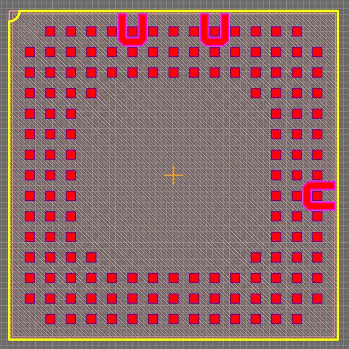
The HE910 family of modems come in a LGA component package. It has selectively depopulated pads. As far as I know, you cannot create one of these packages using the Automatic footprint creator in Altium (the closest you can get is a BGA).
3 of the pads on the footprint have “do not route” areas surrounding three of their sides (these are the main cellular antenna, the optional diversity antenna, and the GPS antenna). Make sure to not include and tracks or ground planes in these areas.

The Antenna
The HE910 comes with no on-board antenna, so you have to provide a connection to your own.
Soldering
The HE910 is designed to withstand only one reflow process, so make sure you get it right. This means on a double-sided board you can’t solder the modem on the first side (assuming you are doing a separate reflow process for each side of the PCB).
Interfacing With A Microcontroller
All of the HE910 pins are CMOS +1.8V tolerant. This makes slightly difficult to integrate with external components (e.g. microcontrollers), which typically run of 3.3V or 5.0V. You can get away with certain connections without level-shifters if you use things like open-drain drivers. Some microcontrollers support configurable voltage level GPIO ports, so this is another way you could interface a microcontroller running of 3.3V to the modem. The modem provides a +1.8V out capable of sourcing 60mA for the extra voltage rail this micro will need.
The HE910 modem provides many different ways of connecting to a host microcontroller.
UART
Telit has named the UART pins on the device as if treating the device like a DCE (a modem), so you do not cross over the TX/RX or other pins when connecting to the microcontroller, instead you must connect the TX to the HE910 to the TX of the microcontroller.
The HE910 can be sent AT commands and have it’s GPS information read through the single primary UART interface. For simple control of the modem, you only need to connect the TxD and RxD lines, using only two wires. For more complex control, you can connect up the flow control pins.
Powering The Device
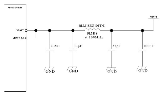
The HE910 can run directly of a Li-Ion battery (3.7V nominal battery voltage). Any other battery chemistry will require buck/boost/lin regulator circuitry to keep the voltage in the allowable range.
The device uses about 40uA when in shutdown. Although this doesn’t seem like much, this can result in a large energy loss in a energy critical application (e.g. battery power). Instead of putting the device into shutdown, it can be better to turn-off the power supply to the HE910 instead (most linear regulators/DC-DC converters support this) instead. However, when doing this, note that you have to pay particular attention to any leakage currents that may occur from any connected devices (e.g. a microcontroller) due to the voltage rail collapsing and the internal ESD diodes conducting.


