UART Communication Protocol

UART (Universal Asynchronous Receiver/Transmitter) is a lower-voltage, microcontroller friendly equivalent of the RS-232 digital data transmission protocol with origins dating back to the 1960’s. It is universal in the sense the timing, voltages, flow control and error checking can be configured.
| Parameter | Value |
|---|---|
| Drive Type | Single-ended |
| Num. Wires (excl. GND) | Commonly just 2 (TX/RX) or 4 (TX/RX and RTS/CTS) |
| Duplexity | Full |
| Connection Topology | Point-to-point |
| OSI Layers | Layers 1 (physical) and 2 (data link) |
It is commonly used today as a simple, two-way node-to-node serial communications protocol between devices on a circuit board or possibly over a cable. Because of it’s low voltage and single-ended nature, it is not very noise resilient, and is usually replaced with a more robust protocol such as RS-232 (higher voltages) or RS-485 (differential signalling) when communication occurs over any significant cable length or in a noisy environment.
Terminology
Bit Period
The bit period is the time (or width) of a single bit in a UART transmission or frame. The bit period is just the reciprocal of the baud rate:
For example, some common baud rates and their corresponding bit periods are:
| Baud Rate | Bit Period |
|---|---|
| 9600 | 104us |
| 57600 | 17.4us |
| 115200 | 8.68us |
Start Bit
The first bit in a UART frame. Always just one bit period wide. The receiver uses the falling (first) edge of the start bit to synchronize it’s sampling clock, the first data bit will be sample 1.5bit periods after this transition.
Stop Bit
The last bit (or bits) in a UART frame. There can be 1, 1.5 or 2 stop bits, with 1 being the most common.
UART Frame Structure
UART sends data in groups of 5, 6, 7 or 8 bits at a time across the bus (typically 8, to equal a single byte) in what is called a UART frame. The bus idles “high” when no data is sent. To indicate the start of a frame, the transmitter drives the line low for one bit period, this is called the start bit. The receiver synchronizes it’s incoming bit sampling clock with the falling edge of the start bit. The start bit lasts for one bit period, and which point the transmitter sends the bits of data by driving the line either high or low. This is then followed by an optional parity bit (which is commonly excluded). Then this is followed by 1, 1.5 or 2 stop bits.
The figure below shows what a UART frame would look like when configured in the popular ‘8n1’ configuration (8 bits, no parity, 1 stop bit):
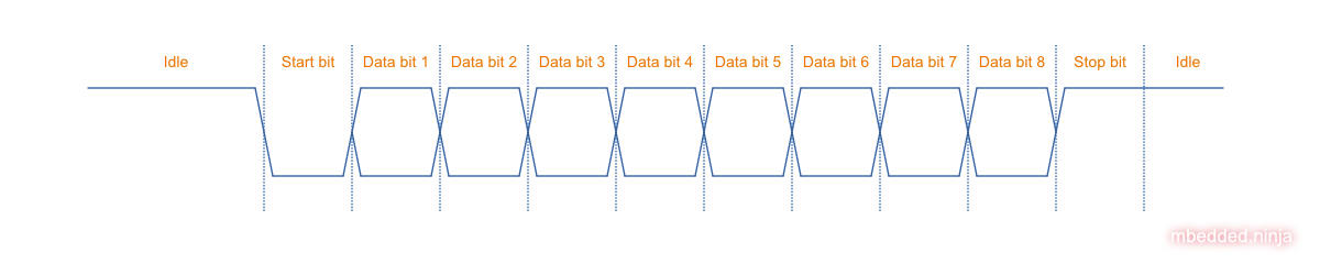
UART has no say in what the data means, it is up to the application code to make sense of one these bits of data mean and to group them into larger data structures.
You might be wondering, why ever have more than 1 stop bit? The answer is that multiple stop bits can be useful to delay the next frame if the receiver needs a little more time to process the current frame.
See the below section on Synchronization for more details on the idle to start bit transition and how the receiver “locks on” to the transmitted data.
Protocol
The long history of RS-232 like serial communication means that UART is synonymous/compatible with many physical and protocol layer variations such as:
- CMOS UART
- RS-232
- RS-423 (differential)
- RS-485 (differential)
- DMX512 (commonly used to control stage lighting and effects)
- MIDI
- LIN Bus
- IrDa
Generally, if someone uses the term UART with no additional context, they are referring to the RS-232 protocol but with voltage levels between VCC and GND, typically created by a UART peripheral in a microcontroller or FPGA.
Connectors
UART is a protocol that has no one single recognizable connector. Because it is commonly used in conjunction with RS-232 or RS-485 protocols, the D subminiature connectors are commonly associated with the UART protocol. However, because UART is a very common microcontroller peripheral and can be used for short, permanent on-PCB communications between microcontroller and 3rd party device, it is also commonly implemented without any connector at all (pin-to-pin on PCB), or is routed from microcontroller directly to 0.1” header pins for things such as debugging (a debug UART is very common on embedded devices).
WARNING: There is confusion of how to connect two RS-232 (or UART!) devices together arises when it is not terminal equipment (DTE) connected to modem equipment (DCE). In the embedded world, microcontrollers and other devices which support RS-232/UART can act either as a DTE or a DCE. Take particular care when connecting RS-232/UART ports together on embedded devices!
Transmission Speeds
UART, by today’s standards, is a slow transmission protocol. However, it is still fast enough for tons of applications. The commonly supported baud rate speeds are:
- 600, 1200, 3400, 4800, 9600, 14400, 19200, 28800, 38400, 56000, 57600, 115200, 128000, 256000, 460800, 921600
I have had basically no issues using speeds up to 460800 baud in embedded systems (either talking to another embedded system, or to a computer through a virtual COM port). However, 921600 baud has not worked for me in some situations.
Out of the baud rates listed above, there are three which are used more than others:
9600: Very common default baud rate for microcontroller development kits such as Arduino.57600: Another common baud rate.115200: Another common default baud rate, offering a 10-fold improvement in data throughput compared to9600. If you are looking for a default baud rate to choose for a new design, I recommend using this speed!
Some devices also support custom baud rates.
Error Checking/Noise Immunity
The only error checking a UART has by specification is parity checking (additional error features may exist).
You may notice when sending lots of characters across a UART that some appear to be corrupted. These can be a real bummer if you are using UART to transmit lots of data (for say a data logging application). The best ways to improve noise immunity are:
- Slow down the transmission rate to the slowest acceptable speed. Far less errors occurs at 9600 baud than say, 57600 baud.
- Enable parity checking (does not completely fix the problem!)
- Enable voting algorithms if the transmitter or receiver support it.
- Similarly, enable oversampling if the transmitter or receiver support it (very similar to voting).
- Make the UART transmission lines as short as possible and with as little capacitance as possible.
- Shield the UART cable (not so important)
- Implement a checksum algorithm into the receiver and transmitter, such as a CRC. The UART protocol does not support this natively, you will have to use a 3rd party library/write the code to do this yourself. Even when using a simple checksum algorithm such as exclusive or (XOR), this is probably one of the most fool proof methods for error checking.
Synchronization
Synchronization problems can arise if data is sent continuously (i.e. with no idle time between blocks of data) from a UART transmitter and the receiver boots up in the middle of the transmission (or otherwise gets reset or loses where it thinks it was). In this case, the receiver may not be able to correctly distinguish the start bit from any of the other bits, as the start and end bits have the same bit width as the data. The receiver may produce incorrect data or signal framing errors until there is enough idle time to “reset” it’s internal state and correctly wait for the next start bit.
Break Signal
The break signal is not a character, but a special signal which can be sent from transmitter to receiver to indicate an event.
The transmitter sends a break signal by driving it’s TX line low for a period longer than one frame. There are two types of breaks, short breaks and long breaks. A short break is when the TX line is driven low for a period of between 1 and 2 frame lengths, and a long break is when it is driven low for a period of more than 2 frame lengths.
Higher-Level Protocols
Do you need a higher-level communication protocol that works over a UART connection? See the SerialFiller library on GitHub (written in C++). SerialFiller uses a publish/subscribe mechanism and works well on point-to-point serial connections such as UART.
Backfeeding Through UART
When using UARTs on microcontrollers, be careful about backfeeding (a.k.a backpowering) devices through the TX line! If a microcontroller loses it’s power rails during normal operation, the TX line connected to the microcontrollers RX can keep it’s VCC afloat by conducting through the internal ESD diodes (remember that in the idle state, the TX line is driven high).
Voltage-level translator ICs are one way to fix this problem. You have make sure they are of the type which make the I/O pins and high-impedance when there is on one or more of the pins. The below image shows how a voltage-translator IC can be used to prevent backfeeding a MCU from a debug UART:
Rather than a voltage-level translating IC, a buffer IC with functionality (this is what Texas Instruments calls a logic IC which won’t backfeed current from the I/O pins into the pins when the VCC pins are at ) will also work — for example, the SN74LVC1G125 (“Single Bus Buffer Gate With 3-State Output”).
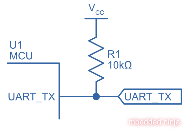
Pull-up Resistors On TX Lines
Spurious garbage can be sent along along a microcontrollers UART TX line when the microcontroller resets. When microcontrollers reset, all of their GPIO pins typically default back to high-impedance inputs. This will cause the voltage on the TX line, typically idling HIGH, to collapse and signal LOW. The UART receiver on the other end of the bus could interpret this as data and give to nonsensical garbage. As shown in the below image, a solution to this is to add a pull-up resistor to , which keeps the TX line HIGH when the microcontroller resets.
Terminal Programs
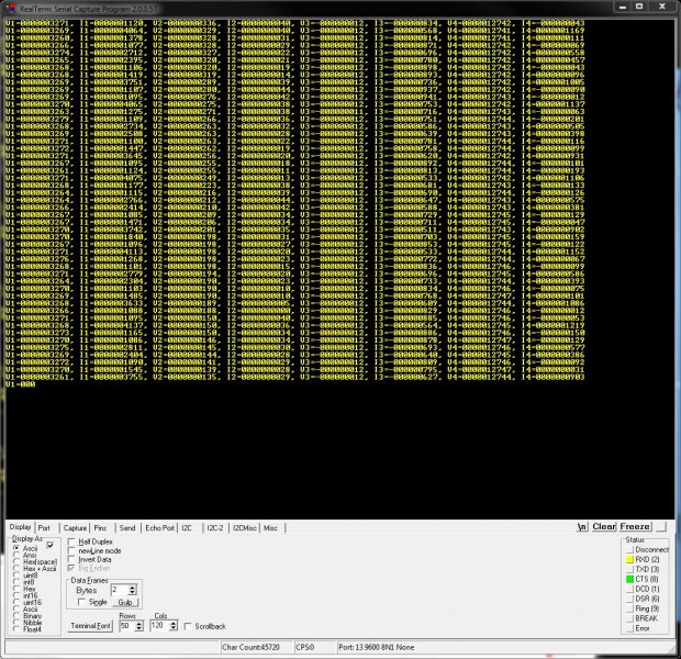
RealTerm (3.5/5)
Website: http://realterm.sourceforge.net/
A easy to use and powerful terminal program for Windows. Stolen from the website, it’s description is:
a terminal program specially designed for capturing, controlling and debugging binary and other difficult data streams. It is far better for debugging comms than Hyperterminal. It has no support for dialing modems, BBS etc - that is what hyperterminal does.
It can view and send binary, hex, ASCII, ANSI, integers (both signed and unsigned, 8 or 16-bit), floats and more. Support for half-duplex communication as well as I2C! Does not lag/hang at all (including when you disable the COM port while it is still running). You can run multiple RealTerm apps at the same time, to get data from multiple UART ports simultaneously. It can add timestamps to received UART messages, which is useful for data logging.
I have noticed a few bugs with RealTerm, especially when it comes to changing the number of rows and columns, and scrolling back through received data (the scrollback variable is buggy also).
UPDATE 2021-05-17: It seems like development on the SourceForge site has stopped long ago. There is a Realterm “Development Version” which can be found at https://realterm.i2cchip.com/, this has updates as recent as 2018.
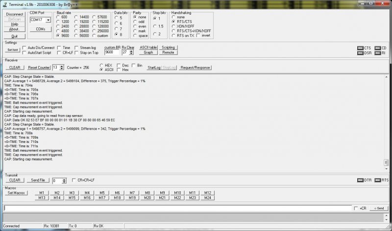
Terminal by Br@y (3.5/5)
Website: https://sites.google.com/site/terminalbpp/
A simple and tidy Windows terminal program. Personally, it doesn’t get the same amount of respect as RealTerm because of it’s simplicity and slightly buggy nature. When decoding into hex, the program can hang if your receiving large amounts of data. It can also hang if you disable the COM port while it is still connected.
PuTTy (4/5)
Website: http://www.chiark.greenend.org.uk/~sgtatham/putty/
PuTTY is a free implementation of Telnet and SSH for Windows and Unix platforms, along with an xterm terminal emulator.
If your running windows, PuTTY is a very handy application to have if you want to emulate the command-line style interface of a UNIX-like system. Although the debugging and capturing features are not as good as say, RealTerm, it offers character-by-character input and proper response to pressing ‘special’ keys such as enter (which RealTerm doesn’t allow, instead you have to enter a string and then press send). This may sound like a very small difference, but this feature does come in useful! I find it very handy when using FreeRTOS and the CLI (command-line interface) extension, which allows you to communicate from a pc to a embedded system using a command-line style interface (as in the picture to the right).
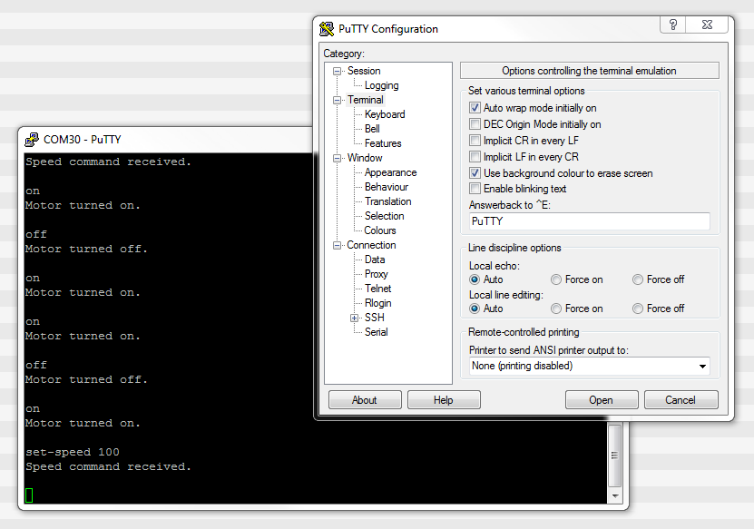
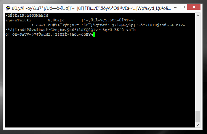
I have discovered one bug in PuTTY…if it receives a large number of characters all at once (which is common when printing debug messages from an embedded system, and for some reason, the string is not null-terminated, and starts printing gobble-de-gooch from random memory locations), PuTTY can freeze, and needs to be restarted. In this situation, it can also print the message “PuTTyPuTTyPuTTy” many times over across the COM port you are debugging. Weird.
9-Bit Addressing
9-bit addressing was employed when using a multi-drop configuration to prevent slaves from wasting processor time in decoding every byte on the bus to see if it was addressed to them. A 9th bit is sent out after every byte, and is used to signal if the previous 8-bits where an address (which the slaves have to listen to), or just data (which can be ignored).
Radiation Hardening
Some UART protocols have radiation tolerant devices, such as the DRS4485, an Dual RS-485 Interface Transceiver made by Aeroflex.
RS-232
RS-232 is a very similar protocol to UART, and a UART to RS-232 converter is one of the most popular communication protocol converters you will see in an embedded system.
For more information, see the RS-232 page.
RS-485
RS-482 is another very common protocol that UART is converted to and from. It is usually chosen over RS-232 when longer distances and/or larger noise immunity is needed. For more information, see the RS-485 page.
Cables
You can get null-terminated USB-to-USB serial port emulator cables. These are awesome for transferring data between two computers (or any 2-USB host devices) without reverting to a true USB-to-USB A cable (which requires use of a more complicated protocol).
FTDI makes one such cable called the USB to USB cable.
If you are interested in routing between two COM ports on the same computer, you could use one of these, however, it is normally much easier to do it purely in software with a serial bridge instead.
There are also USB-to-UART cables for connecting a computer to a UART bus. FTDI is one of the most popular manufacturers of these, and make cables that can both use a Virtual COM port or D2XX drivers. Internally, the cables use FTDI’s FT232RQ IC.1 The internal EEPROM can be reprogrammed to change the VID and PID of the device (they default to 0x0403 and 0x6001 respectively).1 Be aware however that if you do this on Windows (and possibly on other OSes too), the FTDI Virtual COM port driver will not automatically pick it up, and you’ll have to configure this manually. Also, the EEPROM programming utility FT_PROG won’t pick up the device any more!
ICs
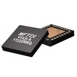
FTDI FT232RNQ
The FTDI FT232RNQ is a USB to UART IC in a QFN-32 or SSOP-28 package. It supports USB 2.0 Full Speed (12 Mbps) and data rates up to 3 Mbaud. It also has 4 GPIO pins which can be controlled from the USB host for auxiliary functions. It supports I/O voltages from 1.8 to 5.5 V.2
See the Controlling FTDI Devices page for more information on how to control these devices from software such as Python and the pyftdi library.
WCH CH340
The WCH (a.k.a. Nanjing Qinheng Microelectronics) CH340 is a family of popular USB to UART ICs. It supports USB 2.0 and serial baud rates from 50 bps to 2 Mbps.3
There are a number of variants in the CH340 family, denoted by an additional letter suffix to the part number:3
- CH340B: SOP-16. Built-in clock. Contains built-in EEPROM for configuration of serial number and other settings.
- CH340C: SOP-16. Built-in clock.
- CH340E: MSOP-10. Built-in clock.
- CH340G: SOP-16. No built-in clock.
- CH340K: ESSOP-10. Built-in clock. 3 built-in diodes to prevent the backflow of current when there are independent power supplies.
- CH340N: SOP-8. Built-in clock.
- CH340R: SSOP-20. No built-in clock. Reverse polarity TXD and modem signals. Discontinued.
- CH340T: SSOP-20. No built-in clock.
- CH340X: MSOP-10. Built-in clock. Like the CH340E, except with improved 5V tolerant IO (+3.3V supply).
WCH CH9344
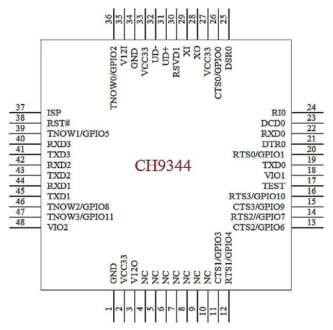
The WCH CH9344 is a USB to Quad UART IC in a LQFP-48 package. It’s USB interface supports USB 2.0. It also provides 12 GPIO pins which can be used for auxiliary functions. UART0 to UART2 have independent voltage rails which can be 1.8V, 2.5V or 3.3V (UART3 is fixed at 3.3V).4
This is a placeholder for the reference: fig-ch9344-usb-to-quad-uart-ic-pinout shows the pinout of the LQFP-48 IC.
https://github.com/WCHSoftGroup/ch9344ser_linux is a Linux driver that supports this IC. The driver creates tty devices named ttyCH9344USBx in your /dev directory.
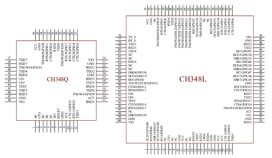
WCH CH348
The WCH CH438 is a USB to 8 UART IC, similar to the WCH CH9344 USB to 4 UART IC. Like the CH9344, the UARTs have independent voltage rails that cna be set to 1.8V, 2.5V or 3.3V. As shown in This is a placeholder for the reference: fig-ch348-usb-to-8-uart-ic-pinout, the IC comes in two different packages. The larger LQFP-100 package provides flow controls pins for every single one of the UARTs.
Power Line Transceivers
The SIG60 is an example of a power line transceiver.
Creating A Serial Port Bridge
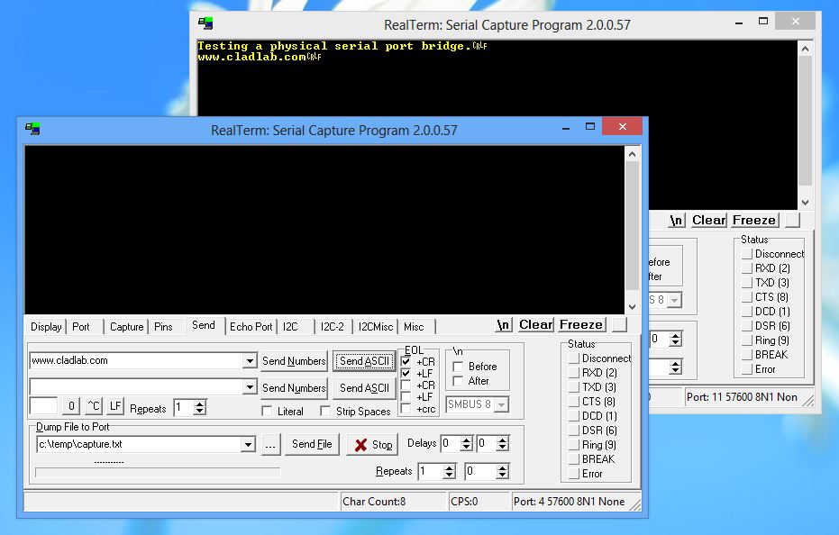
There are occasions when you want or need to send serial data between two pieces of software on the computer, or between two hardware devices both connected to the computer. An example would be to unit test a PC-based serial communications protocol you have written without writing the unit-test code on the microcontroller. There are software programs that emulate a serial port bridge, but in my experience I found these are every buggy or cost money.
You can create a rudimentary serial bridge to connect to pieces of software together by connecting two USB-to-UART (or USB-to-RS232) converters together, crossing the RX and TX lines over. Although not a very permanent solution, this is good for simple tests. This is a placeholder for the reference: fig-testing-a-physical-serial-port-bridge shows a hardware-based serial port bridge with a terminal on each end.
Footnotes
-
FTDI. USB to RS232 Serial Converter Range of Cables [datasheet]. Retrieved 2025-02-10, from https://ftdichip.com/wp-content/uploads/2023/07/DS_USB_RS232_CABLES.pdf. ↩ ↩2
-
FTDI Devices. Products > FT232RNQ [product page]. Retrieved 2025-12-02, from https://ftdichip.com/products/ft232rnq/. ↩ ↩2
-
WCH. USB to Serial Port Chip CH340. Version 3D. [datasheet]. Retrieved 2025-10-09, from https://www.wch-ic.com/downloads/CH340DS1_PDF.html. ↩ ↩2
-
WCH. USB to Quad UARTs Chip CH9344 [datasheet]. Retrieved 2025-08-04, from https://www.wch-ic.com/downloads/CH9344DS1_PDF.html. ↩ ↩2
-
Jean-Luc Aufranc (2022, Mar 4). WCH CH348 is an 8-port USB to serial chip with up to 48 GPIOs. CNX Software. Retrieved 2025-08-04, from https://www.cnx-software.com/2022/03/04/wch-ch348-8-port-usb-to-serial-chip-with-up-to-48-gpios/. ↩