Removing Mains Noise from ADC Measurements

This page explores how mains noise can cause aliasing in ADC measurements when using a microcontroller to measure a signal. Noise in the analogue domain can cause aliasing in the digital domain, which can be a problem in a number of applications. This includes any PCB which contains both mains and low-voltage electronics, industrial sensors, audio applications, and others.
We’ll use a simulation to explore the problem. Let’s pretend we are measuring a voltage outputted from a temperature sensor. The temperature is currently not changing, but we have two types of noise:
- Mains noise - This is the 50/60Hz noise from the power lines.
- Random noise - This is random noise from the sensor.
Let’s simulate our signal from the temperature sensor. First off, we’ll start with a simple constant 2V signal. Then we’ll add the following random noise:
- Shape: Gaussian
- Standard deviation: 100mV
- Mean: 0mV (i.e. centered around 0)
And we’ll also add the following mains noise:
- Shape: Sine wave
- Frequency: 50Hz (mains can also be 60Hz depending on where you are in the world)
- Peak-to-peak: 20mV (10mV amplitude)
When we add the 2V output with the random noise and the mains noise, we get the signal shown in This is a placeholder for the reference: fig-analogue-signal. This is the signal in the analogue domain. This is the signal which the ADC will see and sample from.
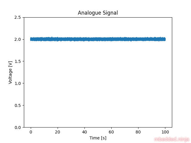
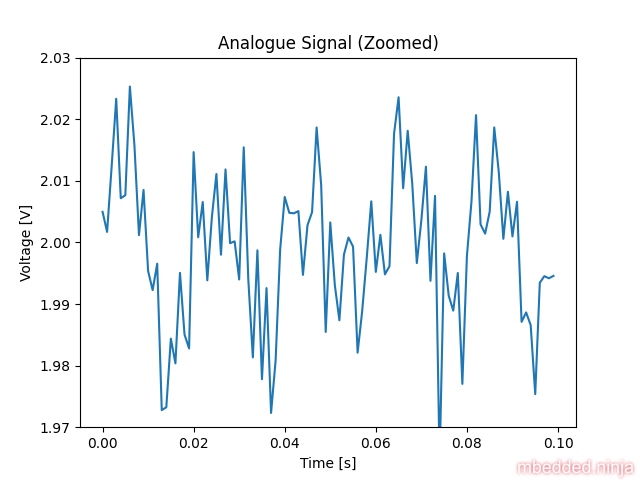
We can see that there is noise, but you can’t really see the nature of the noise zoomed this far out. This is a placeholder for the reference: fig-analogue-signal-zoomed shows a version zoomed into the first 100ms (and zoomed in on the y-axis also).
Digital Sampling and Aliasing
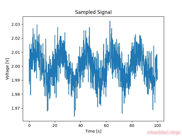
Now let’s see what happens when we sample this signal with an ADC. We’ll set the sampling interval so that it is almost a integer multiple of the mains period (), but not quite. We are doing this to deliberately exacerbate the aliasing effect to produce very low frequency noise on the output, which will be hard to filter! Let’s choose , which is very close to 5 mains cycles ().
A period of is a frequency of:
The closest integer multiple of this to the mains frequency is:
So the aliasing frequency should be:
This means we should expect a ( period) component in our sampled signal. This is a placeholder for the reference: fig-sampled-signal-with-noise shows the sampled signal by our ADC. Indeed, we can see a strong frequency component with a period.
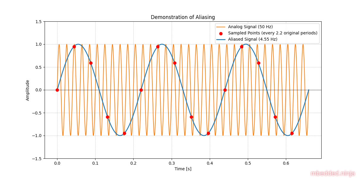
You can clearly see some really low frequency noise in this sampled signal. This is due to the aliasing effect. It might be worth touching on how aliasing works here. Explaining it in detail is beyond the scope of this article, but This is a placeholder for the reference: fig-aliasing-demonstration shows a demonstration of aliasing. The yellow line is the analogue signal, and the red dots are the sampled points by the ADC (we are sampling every 2.2 periods of the original signal, which is 22.7Hz). The blue line is the resulting “aliased” signal we would see in the digital domain.
So now that we are in the digital domain, let’s try and filter out the noise. We have to solve this using firmware now, so we will use a simple EMA filter to do this (they are great little filters which don’t require a buffer and are cheap to compute). Let’s set and see what happens. This is a placeholder for the reference: fig-filtered-signal shows the signal after filtering.
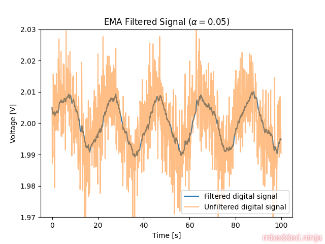
Not good! The noise frequency is so low that it is still very present in the signal. Decreasing to make the filter more aggressive would eventually remove the noise. However, we don’t want to do this as we’ll also start filtering the signal we want to keep, i.e. the temperature changing slowly over time.
Fix 1: Add Jitter to the Sampling
One of the easiest ways to fix this problem in firmware is to add random jitter to the sampling interval. This will cause the aliasing to be in a random location each time, meaning there is no chance that the noise ends up aliasing down to a signal frequency.
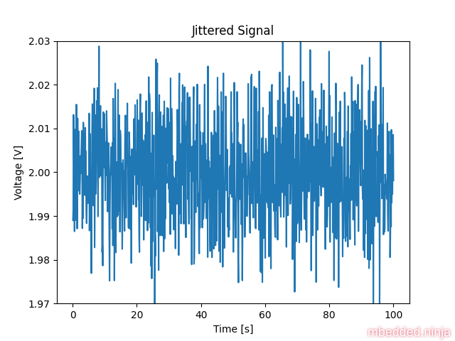
Let’s add some jitter to the sampling interval. We’ll keep the same “average” sampling interval of 100ms, but we’ll add a uniformly random number between -20 and 20ms to this, so that the sampling interval is somewhere between 80 and 120ms.
This is a placeholder for the reference: fig-jittered-signal shows the signal after adding the jitter. You can see that it’s still noisy, but there is no obvious low frequency noise present. This now makes it easy to filter out.
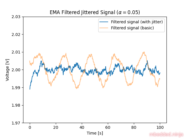
Let’s use the same EMA filter as before. This is a placeholder for the reference: fig-jittered-filtered-signal shows the signal after filtering. This is much better than with no jitter.
Fix 2: Sample in Phase with Mains
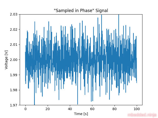
The second way of fixing this problem is to sample the signal in phase with the mains signal. This will mean that there will be no aliasing of the mains noise. There are ICs you can buy which monitor the mains voltage and provide digital outputs when the voltage crosses 0V (zero-crossing detection). You can feed this signal into a microcontroller and use an interrupt to trigger the ADC sampling.
With this approach, you need to make sure you are sampling as consistently as possible with the zero-crossing signal. This might mean that you need to move you ADC sampling from in a thread to in an interrupt handler. Remember to think about any potential latency issues this might cause for the rest of your firmware application.
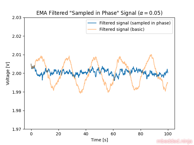
Let’s re-run the simulation, but this time sampling every 100ms. This will be in phase with the mains signal which has a period of 20ms. This is a placeholder for the reference: fig-sampled-in-phase-signal shows the signal after sampling in phase with the mains.
Let’s filter this signal with the same EMA filter as before. This is a placeholder for the reference: fig-filtered-sampled-in-phase-signal shows the signal after filtering.
Fix 3: Increase the Sampling Rate
Another way to fix this aliasing problem is to increase the sampling rate. For no aliasing to occur, your sampling rate () must be greater than or equal to twice the highest frequency component () in the signal (i.e., ). The frequency is known as the Nyquist frequency, and all signal components you wish to capture accurately must be below or equal to this. So if we wanted to get rid of 50Hz aliasing, we would need to sample at a rate greater than or equal to 100Hz.
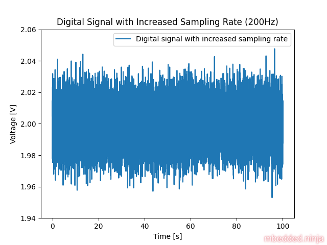
Let’s re-run the simulation, but this time sample at 200Hz (giving ourselves some healthy margin above Nyquist). This is a placeholder for the reference: fig-increased-sampling-rate-digital-signal shows the sampled digital signal after sampling at 200Hz.
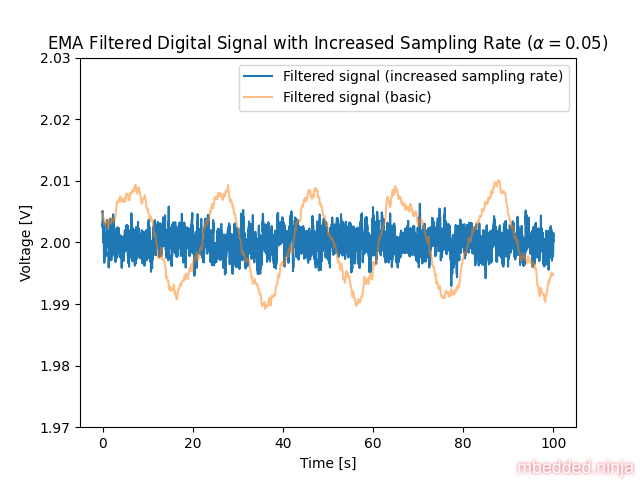
Now let’s filter this signal with the same EMA filter as before. This is a placeholder for the reference: fig-increased-sampling-rate-filtered-signal shows the signal after filtering.
Fix 4: Add an Anti-Aliasing Filter
So far, we have discussed ways of solving the problem in firmware. This is great if you have already made the hardware and it is too expensive to change it. It’s worth mentioning though that one of the best approaches is to just add an anti-aliasing filter to the ADC input.
An anti-aliasing filter is just a low-pass filter which attenuates any frequency components above half the sampling frequency. This eliminates (well, “significantly reduces” given no filter is perfect!) the effects of aliasing. A simple RC low-pass filter is usually all you need unless you need sharp cut-off.
This removes the noise while it is still at a much higher frequency than the signal we want to keep. This is the best place to do it. Once the signal is in the digital domain, the noise has been aliased “down” into the valid signal frequency range and is much harder to remove.
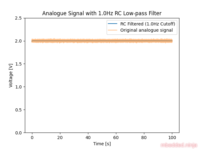
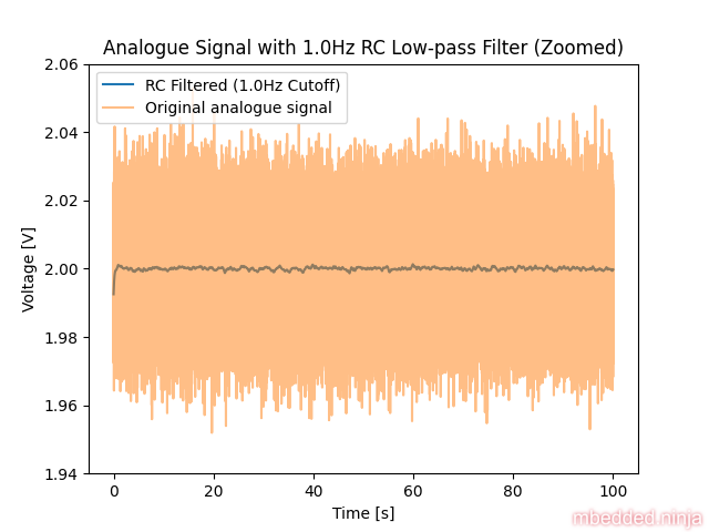
Let’s simulate the addition of a simple low-pass RC filter with the cut-off frequency of 1Hz to the analogue signal, before it enters the ADC. We choose a value of 1Hz so that is much lower than the Nyquist frequency of 5Hz (we have a 100ms sampling interval, which is 10Hz, so half the sampling frequency is 5Hz). This makes sure no really noticeable aliasing occurs.
This is a placeholder for the reference: fig-analogue-signal-rc-filtered shows the signal after the filter. It looks much cleaner than the original signal. In fact, we can no longer see the noise at this zoom level.
Let’s zoom in so we can see the noise. This is a placeholder for the reference: fig-analogue-signal-rc-filtered-zoomed shows the signal after the filter.
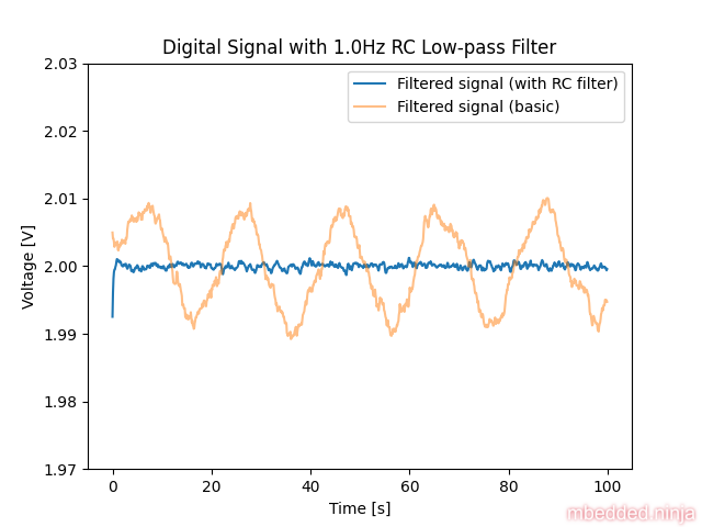
Now let’s see what happens when we sample this signal. It should be pretty obvious that this is going to work a lot better. This is a placeholder for the reference: fig-digital-signal-rc-filtered shows the signal after sampling. Yay! No aliasing. And note that this is not even filtered in the digital domain, which we probably don’t have to do any more.
Conclusion
So what technique is best? If you haven’t finalized the hardware, I would recommend adding an anti-aliasing filter in the analogue domain. This prevents there from being any aliasing problem to begin with.
If you already have 500 PCBs manufactured and need a solution fast, then a firmware solution is probably your best bet. If you can just turn up the sampling rate, then this is probably the best solution, on the conditions that:
- You can increase the sampling rate so it’s at least twice the highest frequency in the analogue signal.
- You have enough CPU cycles to do the sampling and filtering at this rate.
If that isn’t an option, then you can either add jitter or sample in phase with the mains signal. Adding jitter will usually be the easiest solution, as it does not require any zero-crossing detection circuitry. Jitter might be best first approach to see if it works “well enough” for your application. If you want to be more precise, then sampling in phase with the mains signal could give you better results.
Footnotes
-
Stack Exchange - Electrical Engineering (2020, Jan 30). Is a low pass RC circuit the same thing as a first order Butterworth filter? [forum post]. Retrieved 2025-05-10, from https://electronics.stackexchange.com/questions/478610/is-a-low-pass-rc-circuit-the-same-thing-as-a-first-order-butterworth-filter. ↩