Zephyr Peripherals

Not only does Zephyr provide you with an RTOS, but it also gives you a collection of well defined APIs for interacting with microcontroller peripherals. Zephyr rather appropriately calls these APIs “drivers”.
This page aims to cover Zephyr’s drivers and show examples on how to use them.
The latest documentation for peripherals (UART, SPI, PWM, PIN, e.t.c.) APIs can be found at https://docs.zephyrproject.org/latest/reference/peripherals/index.html. Some of Zephyr’s own documentation on drivers is great and teaches you by example, and other drivers are not so well written and you have to piece together code snippets littered all over the place. The automated Doxygen generation is pretty decent, but is only really useful once you know the basics — it doesn’t serve as a great intro in a driver’s API and how to use it.
Hardware Info
The Zephyr Hardware Info API can be used to access the device ID and reset cause of a microcontroller. The reset cause comes from a list of standardised reasons that apply to most microcontrollers such as reset pin, a software reset, a watchdog timer reset, brownout reset, debug event, e.t.c (not all reset causes may be applicable to a particular microcontroller).
hwinfo_get_reset_cause() sets a uint32_t with each bit representing a different reason for reset (a bit field). More than 1 bit can be set. Below is a C function which decodes the reset cause bit field returned from hwinfo_get_reset_cause() and creates a human-readable string of the reset reason(s) (great for logging).
#include <stdint.h>
#include <zephyr/drivers/hwinfo.h>#include <zephyr/logging/log.h>
typedef struct {    uint32_t flag;    char name[20]; // Make sure this is as large as the largest name} resetCauseFlag_t;
/** * @brief This function logs the reset cause in a human-readable manner, obtained via hwinfo_get_reset_cause(). */void LogResetCause(){    uint32_t resetCause;    int resetCauseRc = hwinfo_get_reset_cause(&resetCause);    __ASSERT_NO_MSG(resetCauseRc == 0);
    resetCauseFlag_t resetCauseFlags[] = {        { RESET_PIN, "RESET_PIN" },        { RESET_SOFTWARE, "RESET_SOFTWARE" },        { RESET_BROWNOUT, "RESET_BROWNOUT" },        { RESET_POR, "RESET_POR" },        { RESET_WATCHDOG, "RESET_WATCHDOG" },        { RESET_DEBUG, "RESET_DEBUG" },        { RESET_SECURITY, "RESET_SECURITY" },        { RESET_LOW_POWER_WAKE, "RESET_LOW_POWER_WAKE" },        { RESET_CPU_LOCKUP, "RESET_CPU_LOCKUP" },        { RESET_PARITY, "RESET_PARITY" },        { RESET_PLL, "RESET_PLL" },        { RESET_CLOCK, "RESET_CLOCK" },        { RESET_HARDWARE, "RESET_HARDWARE" },        { RESET_USER, "RESET_USER" },        { RESET_TEMPERATURE, "RESET_TEMPERATURE" },    };
    const uint32_t buffSize = 100;    char resetReasonBuffer[buffSize];    resetReasonBuffer[0] = '\0'; // Set the initial byte to 0 so that strncat will work correctly    uint32_t currLength = 0;
    for(int i = 0; i < sizeof(resetCauseFlags) / sizeof(resetCauseFlag_t); i++)    {        if(resetCause & resetCauseFlags[i].flag)        {            // Append reset cause string to message            strncat(resetReasonBuffer, resetCauseFlags[i].name, buffSize - currLength);            currLength = strlen(resetReasonBuffer);
            // Add ", " between reasons            strncat(resetReasonBuffer, ", ", buffSize - currLength);            currLength = strlen(resetReasonBuffer);        }    }
    LOG_INF("Reset reason as a bit field: 0x%04X. This means the following flags were set: %s", resetCause, resetReasonBuffer);
    // Clear the reset cause    resetCauseRc = hwinfo_clear_reset_cause();    __ASSERT_NO_MSG(resetCauseRc == 0);}
GPIO
To setup a single GPIO pin your device tree, you can add the following to your .dts file:
my_gpio { # Pin 7 in GPIO controller bank 0 gpios = <&gpio0 7 GPIO_ACTIVE_HIGH>;};You can then get access to this GPIO from your C code with:
const struct gpio_dt_spec myGpio = GPIO_DT_SPEC_GET(DT_PATH(my_gpio), gpios);
bool boolRc = gpio_is_ready_dt(&myGpio);__ASSERT_NO_MSG(boolRc);
GPIO Outputs
You can statically configure your GPIO as an output in your .dts file by using compatible = "gpio-leds";:
/ {    gpio_outputs {        // It doesn't sound right but we use gpio-leds for general I/O outputs        compatible = "gpio-leds";
my_gpio { gpios = <&gpio0 7 GPIO_ACTIVE_HIGH>; label = "My GPIO"; }; };};You can configure a GPIO as an output at runtime (my preferred method, I don’t like the device tree!) in C with:
int intRc = gpio_pin_configure_dt(&myGpio, GPIO_OUTPUT_INACTIVE);__ASSERT_NO_MSG(intRc == 0);The above code gets the device tree spec based of it’s path, checks that the GPIO is ready for use (I’m not sure why it wouldn’t me, but good practice!) and then configures it as an output. To then set the pin high or low, you use gpio_pin_set_dt():
int rc = gpio_pin_set_dt(&myGpio, 0); // Set it low__ASSERT_NO_MSG(rc == 0);
rc = gpio_pin_set_dt(&myGpio, 1); // Set it high__ASSERT_NO_MSG(rc == 0);
GPIO_OUTPUT_LOW and GPIO_OUTPUT_HIGH both set the physical state of the pin, and do not care if the pin is active high or active low. GPIO_OUTPUT_INACTIVE and GPIO_OUTPUT_ACTIVE take into account whether the pin is active high or active low. In the case the pin is active high, setting the pin to a logical level of INACTIVE results in a physical LOW, and ACTIVE is HIGH. In the case it is active low, INACTIVE
If you are using a Nordic MCU with NFC pins (e.g. NFC1, NFC2) make sure to disable NFC with CONFIG_NFCT_PINS_AS_GPIOS=y in your prj.conf if you want to use these pins for GPIO (or anything else for that matter, including PWM).
The gpio_pin_configure_dt() function can also accept SoC specific flags. Some use cases for SoC specific flags are for configuring things like drive strength and enabling internal pull-up/pull-down resistors. For example, the following code is used to configure a GPIO pin in the nRF52 SoC family with high drive (when both low or high):
#include <zephyr/dt-bindings/gpio/nordic-nrf-gpio.h> // Needed for the NRF_GPIO_DRIVE_H0H1 macro
int rc = gpio_pin_configure_dt(&myGpio, GPIO_OUTPUT_HIGH | NRF_GPIO_DRIVE_H0H1);__ASSERT_NO_MSG(rc == 0);
You can read more information about nRF specific flags on the nRF52 page.
GPIO Configuration Errors
If you accidentally try and configure a GPIO pin incorrectly, you might get a runtime error like the following (this was printed to the shell):
ASSERTION FAIL [(cfg->port_pin_mask & (gpio_port_pins_t)(1UL << (pin))) != 0U] @ WEST_TOPDIR/external/zephyr/include/zephyr/drivers/gpio.h:1019
Unsupported pin
This happened to me when I was trying to use a pin that was reserved in the .dts file with the gpio-reserved-ranges property:
&gpio0 { status = "okay"; gpio-reserved-ranges = <0 2>, <6 1>, <8 3>, <17 7>;};GPIO Inputs
To read the value of a GPIO input, use gpio_pin_get_dt():
int rc = gpio_pin_get_dt(&myGpio);__ASSERT_NO_MSG(rc >= 0); // 0 or 1 for low/high, negative number for error
if (rc == 0) {    LOG_INF("GPIO was low.");} else if (rc == 1) {    LOG_INF("GPIO was high.");}
You can also read the current value of a GPIO output using gpio_pin_get_dt(). HOWEVER — you must make sure to provide the GPIO_INPUT flag along with the appropriate output flag when configuring the GPIO pin. For example:
int rc = gpio_pin_configure_dt(&myGpio, GPIO_OUTPUT_LOW | GPIO_INPUT);__ASSERT_NO_MSG(rc == 0);
// Now you can read the value of the GPIO output!int value = gpio_pin_get_dt(&myGpio);
GPIO Interrupts
If you want to configure an interrupt for a GPIO pin, you can use gpio_pin_interrupt_configure_dt():
intRc = gpio_pin_interrupt_configure_dt(&myGpio, GPIO_INT_EDGE_TO_ACTIVE);__ASSERT_NO_MSG(intRc == 0);You then need to setup a callback:
static struct gpio_callback gpioCallbackData;
void GpioCallback(const struct device* dev, struct gpio_callback* cb, gpio_port_pins_t pins){    // GPIO interrupt callback}
int main() {    gpio_init_callback(&gpioCallbackData, &GpioCallback, BIT(myGpio.pin));    gpio_add_callback(myGpio.port, &gpioCallbackData);}
There are many interrupt configuration flags to choose from, including both physical (actual voltage at the pin) and logical (depends on the pin’s active high or active low configuration) triggers. For both physical and logical, there are both edge (transition) and level triggers. This is a placeholder for the reference: tbl-gpio-interrupt-config-flags lists the different flags1.
| Flag | Description | Physical or Logical |
|---|---|---|
GPIO_INT_DISABLE | Disable interrupts for the GPIO pin. | n/a |
GPIO_INT_EDGE_RISING | Trigger interrupt on rising edge. | Physical |
GPIO_INT_EDGE_FALLING | Trigger interrupt on falling edge. | Physical |
GPIO_INT_EDGE_BOTH | Trigger interrupt on both rising and falling edges. | Physical |
GPIO_INT_LEVEL_LOW | Trigger interrupt when the GPIO pin is low. | Physical |
GPIO_INT_LEVEL_HIGH | Trigger interrupt when the GPIO pin is high. | Physical |
GPIO_INT_LEVEL_TO_INACTIVE | Trigger interrupt when pin changes to inactive (logical level 0). | Logical |
GPIO_INT_LEVEL_TO_ACTIVE | Trigger interrupt when pin changes to active (logical level 1). | Logical |
GPIO_INT_LEVEL_INACTIVE | Trigger interrupt when pin is inactive (logical level 0). | Logical |
GPIO_INT_LEVEL_ACTIVE | Trigger interrupt when pin is active (logical level 1). | Logical |
See https://github.com/ubieda/zephyr_button_debouncing/tree/master for an example of using a Zephyr GPIO to handle button presses along with debouncing using a delayable work queue.
The interrupt callback object has not provision for storing user data (e.g. a void *, so you could pass it the “object” that was associated with the interrupt). However, you can use the CONTAINER_OF macro to do almost the same thing, as long as you store the interrupt callback object in the “object”. The following example shows how to do this:
struct {    struct gpio_callback myCallback;} MyObject;
int main() {    MyObject myObject;    gpio_pin_interrupt_configure(myGpio.port, myGpio.pin, GPIO_INT_EDGE_TO_ACTIVE);    gpio_init_callback(&myObject.myCallback, &GpioCallbackHandler, BIT(myGpio.pin));    gpio_add_callback(myGpio.port, &myObject.myCallback);}
static void GpioCallbackHandler(const struct device* dev, struct gpio_callback* cb, gpio_port_pins_t pins){    // Can get "user data" from inside the handler function by using the CONTAINER_OF macro    MyObject* myObject = CONTAINER_OF(cb, MyObject, myCallback);}
If using CONTAINER_OF in C++ to access a containing class instance you might get a compiler warning:
warning: 'offsetof' within non-standard-layout type 'MyClass' is conditionally-supported [-Winvalid-offsetof]In this case, the solution is to create a smaller struct within your class which only contains the gpio_callback and a pointer to MyClass. This will ensure it is a standard layout type. Here is a simplified example which shows how to do this:
struct GpioCallbackDataAndObject {    GpioReal* m_obj;    struct gpio_callback m_gpioCallbackData;};
class MyClass {public:  // ... other members ...  GpioCallbackDataAndObject m_gpioCallbackDataAndObject;};
int main() {  MyClass myClass;  gpio_pin_interrupt_configure(myGpio.port, myGpio.pin, GPIO_INT_EDGE_TO_ACTIVE);  gpio_init_callback(&myClass.m_gpioCallbackDataAndObject.m_gpioCallbackData, &interruptCallback, BIT(myGpio.pin));  gpio_add_callback(myGpio.port, &myClass.m_gpioCallbackDataAndObject.m_gpioCallbackData);}
static void interruptCallback(const struct device* dev, struct gpio_callback* cb, gpio_port_pins_t pins){    // WARNING: This will be called in a interrupt context.    // CONTAINER_OF() won't give the "non-standard layout" warning now since `GpioCallbackDataAndObject` is a standard layout type.    GpioCallbackDataAndObject* gpioCallbackDataAndObject = CONTAINER_OF(cb, GpioCallbackDataAndObject, m_gpioCallbackData);    MyClass * obj = gpioCallbackDataAndObject->m_obj;    // Now we have the object, do something with it!}
Configuring and Setting GPIO In the Shell
Zephyr has a built-in shell command that can be used for configuring and setting GPIO pins. You can enable it by adding the following to your prj.conf file:
CONFIG_GPIO_SHELL=y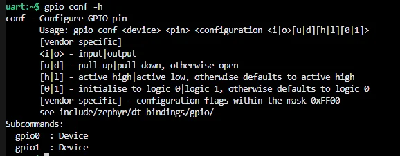
GPIO Reserved Ranges
You can configure reserved ranges of GPIO pins per bank in your .dts file with the gpio-reserved-ranges property. For example:
&gpio0 { status = "okay"; gpio-reserved-ranges = <0 2>, <6 1>, <8 3>;};gpio-reserved-ranges takes a list of ranges, where each range is a tuple of the start pin and the number of pins to reserve. For example, the above configuration reserves pins 0, 1, 6, 8, 9 and 10.
GPIO Line Names
You can assign line names to GPIOs in your .dts file with the line-names property. For example:
&gpio0 { status = "okay"; gpio-line-names = "XL1", "XL2", "AREF", "A0", "A1", "RTS", "TXD", "CTS", "RXD", "NFC1", "NFC2", "BUTTON1", "BUTTON2", "LED1", "LED2", "LED3", "LED4", "QSPI CS", "RESET", "QSPI CLK", "QSPI DIO0", "QSPI DIO1", "QSPI DIO2", "QSPI DIO3","BUTTON3", "BUTTON4", "SDA", "SCL", "A2", "A3", "A4", "A5";};PWM
For example, looking at zephyr/dts/arm/nordic/nrf52832.dtsi and searching for “pwm” we find:
/ { soc { pwm0: pwm@4001c000 { compatible = "nordic,nrf-pwm"; reg = <0x4001c000 0x1000>; interrupts = <28 NRF_DEFAULT_IRQ_PRIORITY>; status = "disabled"; #pwm-cells = <3>; }; pwm1: pwm@40021000 { compatible = "nordic,nrf-pwm"; reg = <0x40021000 0x1000>; interrupts = <33 NRF_DEFAULT_IRQ_PRIORITY>; status = "disabled"; #pwm-cells = <3>; }; pwm2: pwm@40022000 { compatible = "nordic,nrf-pwm"; reg = <0x40022000 0x1000>; interrupts = <34 NRF_DEFAULT_IRQ_PRIORITY>; status = "disabled"; #pwm-cells = <3>; }; }}In your .dts file, we first need to override the pwm0 with some parameters:
&pwm0 { status = "okay"; pinctrl-0 = <&pwm0_default>; pinctrl-1 = <&pwm0_sleep>; pinctrl-names = "default", "sleep";};Notice how the mapping between the PWM channels and the pins is not directly set here (some examples online directly assign pins here), instead pointing to some structures defined in the pin control file. So then in your pin control file, we need to define the mapping between the PWM channels and the pins. For example:
&pinctrl {    pwm0_default: pwm0_default {        group1 {            psels =                <NRF_PSEL(PWM_OUT0, 0, 10)>, // Assign pwm0 channel 0 to port 0, pin 10                <NRF_PSEL(PWM_OUT1, 0, 5)>, // Assign pwm0 channel 1 to port 0, pin 5            nordic,invert;        };    };
    pwm0_sleep: pwm0_sleep {        group1 {            psels =                <NRF_PSEL(PWM_OUT0, 0, 10)>, // Assign pwm0 channel 0 to port 0, pin 10                <NRF_PSEL(PWM_OUT1, 0, 5)>, // Assign pwm0 channel 1 to port 0, pin 5            low-power-enable;        };    };}
my_pwm_group { compatible = "pwm-leds"; status = "okay"; my_pwm_pin_1 { // Use pwm peripheral 0 and channel 0 pwms = <&pwm0 0 PWM_MSEC(5) PWM_POLARITY_NORMAL>; }; my_pwm_pin_2 { // Use pwm peripheral 0 and channel 1 pwms = <&pwm0 1 PWM_MSEC(5) PWM_POLARITY_NORMAL>; };};This defines 3 PWM peripherals.
PWM can be set up with:
const struct pwm_dt_spec myPwmSpec = PWM_DT_SPEC_GET(DT_PATH(my_pwm_group, my_pwm_pin_1));
boolRc = pwm_is_ready_dt(&myPwmSpec);__ASSERT_NO_MSG(boolRc);
And then enabled with:
// This will enable the PWM with a period of 1000us and a pulse width of 500us (i.e. 50% duty cycle)int intRc = pwm_set_dt(&myPwmSpec, PWM_USEC(1000), PWM_USEC(500));__ASSERT_NO_MSG(intRc == 0);ADCs
The Zephyr ADC API lets you sample analogue voltages using the MCU’s ADC peripheral(s).
The Zephyr ADC API is documented here.
There are working ADC examples in the Zephyr repo at samples/drivers/adc/. As of September 2024, there are two examples:
adc_dt: Basic ADC example.adc_sequence: An ADC example showing how to take readings using sequences.
The example below shows how to setup and configure the ADC on a nRF52 device. Some the code, especially the .dts file, will be different between MCUs and vendors. The C code should remain similar (or the same!) since Zephyr aims to provide a standard interface across devices.
prj.conf Configuration
The first thing to do is to add CONFIG_ADC=y to your prj.conf file:
CONFIG_ADC=yThat’s it! The remainder of the configuration is either done in the .dts file or in your C code.
DTS Configuration
First up, you need to enable and configure the ADC in your .dts file. For example:
/ {    zephyr,user {        // NOTE: This zephyr,user bit is not needed if you use the ADC_DT_SPEC_STRUCT(DT_NODELABEL(adc), 0) style to        // grab the ADC channel spec in your C code.        io-channels = <&adc 5>, <&adc 7>;    };};
&adc {    #address-cells = <1>;    #size-cells = <0>;    status = "okay";
    channel@0 {        reg = <0>;        zephyr,gain = "ADC_GAIN_1_4";        zephyr,reference = "ADC_REF_VDD_1_4";        zephyr,acquisition-time = <ADC_ACQ_TIME_DEFAULT>;        zephyr,input-positive = <NRF_SAADC_AIN5>;        zephyr,resolution = <12>;    };
channel@1 { reg = <1>; zephyr,gain = "ADC_GAIN_1_4"; zephyr,reference = "ADC_REF_VDD_1_4"; zephyr,acquisition-time = <ADC_ACQ_TIME_DEFAULT>; //<ADC_ACQ_TIME(ADC_ACQ_TIME_MICROSECONDS,3)>; zephyr,input-positive = <NRF_SAADC_AIN7>; zephyr,resolution = <12>; };};zephyr,gain: Sets the gain for the ADC. In the nRF52 the following are available:ADC_GAIN_1_4: Sets the gain to 1/4.ADC_GAIN_1_6: Sets the gain to 1/6. This is commonly used withADC_REF_INTERNALto measure a range from 0 to 3.6V (0.6V * 6 = 3.6V).
zephyr,reference: Sets the reference voltage for the ADC. In the nRF52 the following are available:ADC_REF_INTERNAL: Sets the reference to the internal 0.6V reference.ADC_REF_VDD_1_4: Sets the reference to 1/4 of the VDD voltage.
This assumes we have two single ended ADC channels connected to pins AIN5 and AIN7.
ADC_REF_INTERNAL results in a range of +-0.6V to the ADC core. ADC_GAIN_1_6 pre-scales the input to 1/6 before applying it to the core.
C Code
There are a number of ways to grab the ADC channel spec from the .dts in your C code. My preferred way is to reference the adc node with DT_NODELABEL(adc) and use ADC_DT_SPEC_STRUCT() to get the spec for a given channel, specifying the channel number as the second argument. If you use this method, you don’t actually need the zephyr,user node in your .dts file.
static struct adc_dt_spec l_myAdcCh0Spec = ADC_DT_SPEC_STRUCT(DT_NODELABEL(adc), 0); // Get 1st channelstatic struct adc_dt_spec l_myAdcCh1Spec = ADC_DT_SPEC_STRUCT(DT_NODELABEL(adc), 1); // Get 2nd channelI have has some weird experiences with getting the ADC channel spec with:
static const struct adc_dt_spec adc_channel = ADC_DT_SPEC_GET(DT_PATH(zephyr_user)); // In the case of just a single channel in zephyr,user {}in where the returned spec.channel_cfg was all zeros, indicating is was not set up correctly (and indeed, the adc_channel_setup_dt() would fail). I’m not sure why this is.
Then you can do the following to perform a ADC reading:
bool isReady = adc_is_ready_dt(l_myAdcCh0Spec);__ASSERT(isReady, "ADC channel is not ready.");
int rc = adc_channel_setup_dt(l_myAdcCh0Spec);__ASSERT(rc == 0, "Could not setup ADC channel. Got adc_channel_setup_dt() return code %d.", rc);
int16_t buf = 0;struct adc_sequence sequence = {    .buffer = &buf,    .buffer_size = sizeof(buf), // Buffer size in bytes, not number of samples};
int rc = adc_sequence_init_dt(l_myAdcCh0Spec, &sequence);__ASSERT(rc == 0, "Could not initialize sequence. Got adc_sequence_init_dt() return code %d.", rc);
rc = adc_read(l_myAdcCh0Spec->dev, &sequence);__ASSERT(rc == 0, "Could not read ADC. Got adc_read() return code %d.", rc);
int32_t val_mv = buf; // Save the raw value to val_mv, as required by adc_raw_to_millivolts_dt()rc = adc_raw_to_millivolts_dt(l_myAdcCh0Spec, &val_mv);__ASSERT(rc == 0, "Could not convert raw value to mV. Got adc_raw_to_millivolts_dt() return code %d.", rc);
LOG_INF("ADC channel 0 reading: %d mV", val_mv);
Iterate Automatically Over All Channels
You can also use Zephyr macros like DT_FOREACH_PROP_ELEM() to iterate over all the channels in the zephyr,user node. The following C code shows how to do this:
#include <zephyr/drivers/adc.h>
#define DT_SPEC_AND_COMMA(node_id, prop, idx) \    ADC_DT_SPEC_GET_BY_IDX(node_id, idx),
/* Data of ADC io-channels specified in devicetree. */static const struct adc_dt_spec adc_channels[] = {    DT_FOREACH_PROP_ELEM(DT_PATH(zephyr_user), io_channels,                 DT_SPEC_AND_COMMA)};
int main() {    int rc = 0;
    // Configure channels individually prior to sampling.    for (size_t i = 0; i < ARRAY_SIZE(adc_channels); i++) {        if (!device_is_ready(adc_channels[i].dev)) {            LOG_INF("ADC controller device %s not ready\n", adc_channels[i].dev->name);            return -1;        }
        rc = adc_channel_setup_dt(&adc_channels[i]);        if (rc < 0) {            LOG_INF("Could not setup channel #%d (%d)\n", i, rc);            return -1;        }    }
    // Call our function to perform a measurement    int32_t sample_mV = 0;    rc = SampleChannel(0, NULL, &sample_mV);    __ASSERT_NO_MSG(rc == 0);}
int SampleChannel(uint8_t channelId, int32_t * sample_counts, int32_t * sample_mV){    // We are doing just one measurement, so buffer does not need to be an array    uint16_t buf; // NOTE: Nordic's driver uses int16_t, see below    struct adc_sequence sequence = {        .buffer = &buf,        // buffer size in bytes, not number of samples        .buffer_size = sizeof(buf),    };
    int rc;    rc = adc_sequence_init_dt(&adc_channels[channelId], &sequence);    if (rc)    {        LOG_ERR("Couldn't configure the ADC sequence. adc_sequence_init_dt() rc: %d.", rc);        return -1;    }
    // Perform the actual measurements    rc = adc_read(adc_channels[channelId].dev, &sequence);    if (rc < 0) {        LOG_ERR("Could not read value from ADC. adc_read() rc: %d.", rc);        return -1;    }
    int32_t tempSample_counts = 0;    if (adc_channels[channelId].channel_cfg.differential) {        tempSample_counts = (int32_t)((int16_t)buf);    } else {        tempSample_counts = (int32_t)buf;    }
    // Save raw value if provided pointer    if (sample_counts) {        *sample_counts = tempSample_counts;    }
    // Convert raw sample_mV to mV, more useful to caller    int32_t convertedVoltage_mV = tempSample_counts; // Needs to start of with raw value, function reads then modified it!    rc = adc_raw_to_millivolts_dt(&adc_channels[channelId],                                   &convertedVoltage_mV);    if (rc < 0) {        LOG_ERR("Could not convert ADC reading to mV. adc_raw_to_millivolts_dt() rc: %d.", rc);        return -1;    }
    if (sample_mV) {        *sample_mV = convertedVoltage_mV;    }
    return 0;}
Nordic Semiconductor has a guide on setting the ADC for their nRF MCUs using Zephyr here.
nrfx SAADC Driver
Zephyr’s ADC driver can work with the SAADC peripheral. However, only basic functionality is provided by the Zephyr ADC API. For example, the Zephyr ADC API does not allow you to setup repeated sampling based on a timer connected with the DPPI/PPI. If you want more functionality than what the Zephyr ADC API provides, you can use the lower level nrfx SAADC driver.
Enable the nrfx SAADC driver in your prj.conf file:
CONFIG_NRFX_SAADC=yAnd get access to the API in your C/C++ code by including:
#include <nrfx_saadc.h>We’ll use the IRQ_CONNECT() macro to connect the SAADC interrupt to an ISR:
IRQ_CONNECT(NRFX_IRQ_NUMBER_GET(NRF_SAADC), IRQ_PRIO_LOWEST, nrfx_saadc_irq_handler, 0, 0);Initialize the SAADC with nrfx_saadc_init():
nrfx_err_t status = nrfx_saadc_init(NRFX_SAADC_DEFAULT_CONFIG_IRQ_PRIORITY);__ASSERT(status == NRFX_SUCCESS, "SAADC init failed. nrfx_saadc_init() returned %d.", status);Configure the channel:
nrfx_saadc_channel_t saadcChannel = { .channel_config = { .resistor_p = NRF_SAADC_RESISTOR_DISABLED, .resistor_n = NRF_SAADC_RESISTOR_DISABLED, .gain = NRF_SAADC_GAIN1_6, .reference = NRF_SAADC_REFERENCE_INTERNAL, .acq_time = NRF_SAADC_ACQTIME_3US, // Make sure this is fast enough for your sampling frequency. 3us is one of the fastest options. .mode = NRF_SAADC_MODE_DIFFERENTIAL, // Or NRF_SAADC_MODE_SINGLE_ENDED. If set to differential, you need to set the resistor_p and resistor_n fields. .burst = NRF_SAADC_BURST_DISABLED, }, .pin_p = NRF_SAADC_INPUT_AIN0, .pin_n = NRF_SAADC_INPUT_AIN1, .channel_index = 0,};nrfx_err_t channelConfigRc = nrfx_saadc_channel_config(&saadcChannel);__ASSERT(channelConfigRc == NRFX_SUCCESS, "SAADC differential channel config failed. nrfx_saadc_channel_config() returned %d.", channelConfigRc);Now let’s set the SAADC to advanced mode using the nrfx_saadc_advanced_mode_set() function. We will:
- Prevent continuous mode by setting
start_on_endtofalse. - Set oversampling rate to 16x. This gives us a better SNR. Remember to compensate for this by changing your sampling frequency as needed. The SAADC will sample at the specified sampling frequency, but will only insert 1 reading into the output buffer for every 16 samples. Thus the oversampled frequency is SAMPLE_FREQ / OVERSAMPLING_RATE.
- Disable burst mode.
nrfx_saadc_adv_config_t advConfig = NRFX_SAADC_DEFAULT_ADV_CONFIG;advConfig.internal_timer_cc = INTERNAL_TIMER_CC;advConfig.start_on_end = false; // Set to true for continuous modeadvConfig.oversampling = NRF_SAADC_OVERSAMPLE_16X;advConfig.burst = NRF_SAADC_BURST_DISABLED;
uint32_t channelMask = nrfx_saadc_channels_configured_get();status = nrfx_saadc_advanced_mode_set(channelMask, NRF_SAADC_RESOLUTION_12BIT, &advConfig, adc_saadc_event_handler);__ASSERT(status == NRFX_SUCCESS, "SAADC advanced mode set failed. nrfx_saadc_advanced_mode_set() returned %d.", status);Now we need to provide the SAADC driver with a buffer using nrfx_saadc_buffer_set(). We are not using continuous mode which requires double buffering, so we only call nrfx_saadc_buffer_set() once.
static constexpr size_t NUM_SAMPLES_IN_BUFFER = 10;int16_t sampleBuffer[NUM_SAMPLES_IN_BUFFER];nrfx_err_t status = nrfx_saadc_buffer_set(static_cast<nrf_saadc_value_t*>(sampleBuffer), NUM_SAMPLES_IN_BUFFER);__ASSERT(status == NRFX_SUCCESS, "SAADC buffer set failed. nrfx_saadc_buffer_set() returned %d.", status);I couldn’t find information on what the type of each buffer element should be. I guessed it was int16_t given the resolution can go up to 12 bits and can be differential (e.g. negative values are possible) and it seemed to work for me.
The last thing we need to do is start the SAADC with nrfx_saadc_mode_trigger().
nrfx_err_t status = nrfx_saadc_mode_trigger();__ASSERT(status == NRFX_SUCCESS, "Failed to trigger SAADC mode. nrfx_saadc_mode_trigger() returned %d.", status);This is a non-blocking function. The signal handler provided to nrfx_saadc_advanced_mode_set() will be called when the SAADC has finished sampling with the event NRFX_SAADC_EVT_DONE.
Offset Calibration
You can start an offset calibration with nrfx_saadc_offset_calibrate(). This is recommended before doing any actual measurements. Because we pass in a callback function, this function will not block and will call the callback function when the calibration is complete.
// Start offset calibration// Because we are passing in a callback function and not nullptr, this function will not blocknrfx_saadc_offset_calibrate(adc_saadc_event_handler);Note that the event handler gets called in an interrupt context, so make the logic in the event handler as lightweight as possible (setting flags and deferring work on the data to a thread is a good idea).
nrfx SAADC examples can be found in the Zephyr repo at modules/hal/nordic/nrfx/samples/src/nrfx_saadc. The official nrfx SAADC driver documentation can be found here.
Identifying Error Codes
All of the nrfx SAADC return codes are of type nrfx_err_t. This type is defined in the header file nrfx_errors.h.
If you print the return code as an integer, you will find they are quite large (e.g. 195887115, which is NRFX_ERROR_BUSY) as the enum is offset by NRFX_ERROR_BASE_NUM (which I love because this is set to 0x0BAD0000 --- note the BAD :-D).
I2C Controller
Zephyr provides a API for your MCU to act as an I2C controller. A controller (previously called a master) is the device which controls the communications on the bus, which includes initiating transmissions and sending the clock signal. The other type of API provided is the I2C target API, designed for I2C slave devices. The I2C controller API is the most widely used, and the I2C target API is still considered experimental (as of July 2025).
There are two distinct ways to use the Zephyr I2C controller API.
- Low-level I2C Bus Comms: Grab a handle to the I2C peripheral (
struct i2c_dt_spec) in your C/C++ code. Then you can use a traditionali2c_read()andi2c_write()functions, providing the address of the device you want to communicate with. - High-level I2C Device Comms: This is where you not only define the I2C peripheral in your
.dtsfile, but also define the devices on the bus that you want to communicate with. Then in your C/C++ code, you grab handles to these devices and communicate withread()andwrite()functions that do not need an address (the bus and address is abstracted away into the Zephyr.dtsfile in your board directory).
Low-level I2C Bus Comms
Firstly, enable the I2C drivers in your prj.conf file:
CONFIG_I2C=yYour microcontroller file will already define the I2C peripherals available (e.g. i2c0, i2c1, …). All you have to do is enable them in your .dts file with:
&i2c0 { status = "okay"; pinctrl-0 = <&i2c0_default_alt>; pinctrl-1 = <&i2c0_sleep_alt>; pinctrl-names = "default", "sleep";};And then in the .dtsi file setup pinctrl to define i2c0_default_alt and i2c0_sleep_alt (NOTE: this code includes nRF specific macros, this will be different on other vendor’s MCUs). This defines SDA to use pin 0.0 and SCL to use pin 0.1:
&pinctrl {  i2c0_default_alt: i2c0_default_alt {    group1 {      psels = <NRF_PSEL(TWIM_SDA, 0, 0)>,        <NRF_PSEL(TWIM_SCL, 0, 1)>;    };  };
  i2c0_sleep_alt: i2c0_sleep_alt {    group1 {      psels = <NRF_PSEL(TWIM_SDA, 0, 0)>,        <NRF_PSEL(TWIM_SCL, 0, 1)>;      low-power-enable;    };  };};
Then in your C/C++ code, you can grab a handle to the I2C peripheral with:
#include <zephyr/drivers/i2c.h>
struct device *i2c_dev = device_get_binding(DT_LABEL(DT_NODELABEL(i2c0)));
You can write with int i2c_write(const struct device *dev, const uint8_t *buf, uint32_t num_bytes, uint16_t addr). This writes data synchronously to the bus, and only returns when the write is complete.
Repeated Start
For more complicated transmissions such as a repeated start, you can use the i2c_transfer() function rather than i2c_write()/i2c_read(). It has the following signature:
int i2c_transfer( const struct device *dev, struct i2c_msg *msgs, uint8_t num_msgs, uint16_t addr);Most of these arguments are self-explanatory. The interesting one is msgs, which is an array of struct i2c_msg objects. Each struct i2c_msg contains:
struct i2c_msg {    /** Data buffer in bytes */    uint8_t *buf;
    /** Length of buffer in bytes */    uint32_t len;
    /** Flags for this message */    uint8_t  flags;};
Just like with the basic read/write functions, buf is a pointer to the data you want to send or receive. len is the length of the data in bytes. flags is an OR’d combination of the following flags (bits):
I2C_MSG_WRITE: Set the read/write bit to write in the first byte across the bus. This is the default flag (e.g.0x00).I2C_MSG_READ: Set the read/write bit to read in the first byte across the bus.I2C_MSG_STOP: Send a stop condition after the message.I2C_MSG_RESTART: Send a repeated start after the message.I2C_MSG_ADDR_10_BITS: Use 10 bit addressing. Not supported by all MCUs.
Note that a stop condition will be sent after the last message in a call to i2c_transfer(), regardless of whether you have explicitly set the I2C_MSG_STOP flag or not. This is so that the bus is returned in a “clean” state for the next transaction. This makes it impossible to chain multiple calls of i2c_transfer() together. Instead you must build all of your messages upfront (more memory!) and make a single call to i2c_transfer(). I’m not a huge fan of this design decision, I wish Zephyr gave us a low-level API to send start, stop and repeated start conditions by themselves, along with just sending data. This would be with the understanding it was up to the caller to manage the bus correctly.
Troubleshooting
Need to use the internal driver buffer but its size is insufficient
If you see an error that looks like this:
<err> i2c_nrfx_twim: Need to use the internal driver buffer but its size is insufficient (0 + 32 > 16). Adjust the zephyr,concat-buf-size or zephyr,flash-buf-max-size property (the one with greater value) in the "i2c@40003000" node.Here is what zephyr,concat-buf-size and zephyr,flash-buf-max-size do:2
zephyr,concat-buf-size: Size of a concatenation buffer that the driver is to use for merging multiple same direction I2C messages that have no RESTART or STOP flag between them (see e.g. thei2c_burst_write()function) into one transfer on the bus. This property must be provided when interacting with devices like the SSD1306 display that cannot tolerate a repeated start and address appearing on the bus between message fragments. For many devices a concatenation buffer is not necessary.zephyr,flash-buf-max-size: TWIM peripherals cannot perform write transactions from buffers located in flash. If such buffers are expected to be used with a given instance of the TWIM peripheral, this property must be set to the maximum possible size of those buffers, so that the driver can reserve enough space in RAM to copy there the contents of particular buffers before requesting the actual transfers. If this property is not set to a value adequate for a given application, write transactions may fail for buffers that are located in flash, what in turn may cause certain components, like the DPS310 sensor driver, to not work. It is recommended to use the same value for this property and for thezephyr,concat-buf-sizeone, as both these buffering mechanisms can utilize the same space in RAM.
The error message is telling you that the driver needs a larger buffer to store the data you are trying to write. You can increase the size of the buffer by setting the zephyr,concat-buf-size and zephyr,flash-buf-max-size properties in your .dts file.
UART
Your microcontroller file will already define the UART peripherals available (e.g. uart0, uart1, …). You have to do is enable them in your .dts file, and provide things like the baud rate:
&uart0 { status = "okay"; current-speed = <115200>; pinctrl-0 = <&uart0_default>; pinctrl-1 = <&uart0_sleep>; pinctrl-names = "default", "sleep";};And then configure pinctrl to define the pins that the UART peripheral uses. The following example configures uart0 to use pin 1.3 for TX and pin 1.4 for RX (NOTE: this code includes nRF specific macros, this will be different on other vendor’s MCUs):
&pinctrl {  uart0_default: uart0_default {    group1 {      psels = <NRF_PSEL(UART_TX, 1, 3)>;    };    group2 {      psels = <NRF_PSEL(UART_RX, 1, 4)>;      bias-pull-up;    };  };
  uart0_sleep: uart0_sleep {    group1 {      psels =        <NRF_PSEL(UART_TX, 0, 24)>,        <NRF_PSEL(UART_RX, 1, 0)>;      low-power-enable;    };  };};
I2S
Your microcontroller file will already define the I2S peripherals available (e.g. i2s0, i2s1, …). You have to enable them in your .dts file with:
&i2s0 { status = "okay"; pinctrl-0 = <&i2s0_default_alt>; pinctrl-names = "default";};And then in the pinctrl peripheral you can configure the pins that is20 uses. The following example configures i2s0 to use pin 0.5 for SCK, pin 0.7 for LRCK, pin 0.8 for SDOUT and pin 0.4 for SDIN (NOTE: this code includes nRF specific macros, this will be different on other vendor’s MCUs):
i2s0_default_alt: i2s0_default_alt { group1 { psels = <NRF_PSEL(I2S_SCK_M, 0, 5)>, <NRF_PSEL(I2S_LRCK_M, 0, 7)>, <NRF_PSEL(I2S_SDOUT, 0, 8)>, <NRF_PSEL(I2S_SDIN, 0, 4)>; }; };USB
CDC ACM
Enable the USB device stack with:
CONFIG_USB_DEVICE_STACK=yNon-Volatile Storage
Zephyr provides an feature rich API for storing things in non-volatile storage (e.g. flash memory). The NVS API is provided by #include <zephyr/fs/nvs.h>. It represents elements as id-data pairs.
To protect against data corruption if power is lost mid-write, the library makes sure there is always one complete copy of the data in flash at all times. The flash area is divided into sectors. Elements are written to the first sector until the sector is full, and then the next sector is prepared for writing (i.e. erased). Many sectors can be “active” at once.3
Typically a partition called storage_partition is setup in the main flash for the NVS system to use. This can be defined in the board files.
First, you need to mount the NVS file system onto a flash device:
#define NVS_PARTITION           storage_partition#define NVS_PARTITION_DEVICE    FIXED_PARTITION_DEVICE(NVS_PARTITION)#define NVS_PARTITION_OFFSET    FIXED_PARTITION_OFFSET(NVS_PARTITION)
int main() {    int rc;    struct flash_pages_info info;    struct nvs_fs fs;
    /* define the nvs file system by settings with:      *  sector_size equal to the pagesize,      *  3 sectors      *  starting at NVS_PARTITION_OFFSET      */    fs.flash_device = NVS_PARTITION_DEVICE;    if (!device_is_ready(fs.flash_device)) {        printk("Flash device %s is not ready\n", fs.flash_device->name);        return;    }    fs.offset = NVS_PARTITION_OFFSET;    rc = flash_get_page_info_by_offs(fs.flash_device, fs.offset, &info);    if (rc) {        printk("Unable to get page info\n");        return;    }    fs.sector_size = info.size;    fs.sector_count = 3U;
    rc = nvs_mount(&fs);    if (rc) {        printk("Flash Init failed\n");        return;    }}
Writing Data
Data can be written to the NVS with the nvs_write() function which has the following signature:
ssize_t nvs_write ( struct nvs_fs * fs, uint16_t id, const void * data, size_t len);fs is the file system object we created above. id is a user chosen ID for the data. Think of this as like a path to the file. It is recommended to store each data ID as a constant. It is up to you to make sure they are unique across your application. Below is an example of writing a MyData structure to the NVS.
#define MY_DATA_ID 0 // This is the ID
typedef struct {    uint8_t sensorId;    uint32_t timestamp;    float temperature;} MyData;
int main() {    MyData myData = {.sensorId = 1, .timestamp = k_uptime_get(), .temperature = 24.5};    ssize_t rc = nvs_write(fs, MY_DATA_ID, &myData, sizeof(myData));    __ASSERT_NO_MSG(rc == sizeof(myData));}
On success, nvs_write() will return the number of bytes written. On failure it will return a negative error code as defined by errno.h. Some of the more common error codes are:
-ENOSPC: Not enough space on the flash device.
nvs_write() also checks the ID and incoming data before a write. If the provided data is identical to the data already in flash, no write is performed. This prevents unnecessary flash wear and improves the speed of the operation.
Reading Data
Data can be read from the NVS with the nvs_read() function which has the following signature:
ssize_t nvs_read( struct nvs_fs * fs, uint16_t id, void * data, size_t len);It’s syntax is very similar to nvs_write(). On success, nvs_read() will return the number of bytes read. If the return value is larger than the number of bytes requested, this means that more data is available. On error, a negative error code as defined by errno.h is returned. Here is an example of reading the MyData structure from the NVS.
MyData myData;ssize_t rc = nvs_read(fs, MY_DATA_ID, &myData, sizeof(myData));__ASSERT_NO_MSG(rc == sizeof(myData));Calculating Free Space
nvs_calc_free_space() can be used to calculate the remaining number of bytes that can be still written to the file system.
ssize_t freeSpace = nvs_calc_free_space(fs);__ASSERT_NO_MSG(freeSpace >= 0);printk("Free space: %d bytes\n", freeSpace);On error, nvs_calc_free_space() returns a negative error code as defined by errno.h.
An official code example of the NVS can be found at https://github.com/zephyrproject-rtos/zephyr/blob/main/samples/subsys/nvs/src/main.c[^github-zephyr-nvs-code-example].
Bluetooth
Nordic has contributed significantly to the Zephyr Bluetooth API ever since they adopted Zephyr as their official platform for the nRF52, nRF53 and nRF91 MCU families.
Update the LE Connection Interval
After you are connected, you can call bt_conn_le_param_update() to update the Bluetooth connection interval. This is useful if you want to save power by increasing the connection interval when you don’t need to send/receive data as often.
struct bt_le_conn_param conn_param = { .interval_min = (708), .interval_max = (800), .latency = (0), .timeout = (400), };int rc = bt_conn_le_param_update(conn, &conn_param);__ASSERT_NO_MSG(rc == 0);conn is a pointer to a struct bt_conn which is the connection object. It’s assumed you have that handy to pass in! The connection interval is in units of 1.25ms, so the above code sets the connection interval min. to 885ms and the max. to 1000ms. By default the min. and max were set to 15ms and 30ms respectively, so this is a significant slow down and results in good power savings for small battery powered devices. The timeout is in units of 10ms, so the above code sets the timeout to 4s. You can use the helper macro BT_LE_CONN_PARAM() to create the struct bt_le_conn_param object if you want.
If you are a Bluetooth central device, these settings will take effect. If you a peripheral device, these settings are “suggestions”. They are sent to the central device and it is up to the central device to accept them. The central device may reject them or choose other values.
Hardware and Software Watchdog
Zephyr provides a software and hardware based watchdog API you can use to monitor your threads and perform actions (usually a system reset) in the case that your threads become unresponsive and do not feed the watchdog in time. The API provides the ability to monitor multiple application threads at once via it’s software watchdog. This software watchdog can in turn be monitored by a hardware watchdog. A hardware watchdog (i.e. a physical peripheral provided by the MCU) can be trusted to reliably reset the device, even if the software watchdog locks up (which can be the case with certain errors).
Hardware Watchdog
To enable the hardware watchdog, first add the following to your prf.conf:
CONFIG_WATCHDOG=yYou don’t normally need to change anything in your boards .dts file, as the watchdog peripheral is usually already enabled (status = "okay") and labeled with wdt0. For example, zephyr/dts/arm/nordic/nrf52840.dtsi contains the following definition for the hardware watchdog on the nRF52840 SoC:
wdt: wdt0: watchdog@40010000 { compatible = "nordic,nrf-wdt"; reg = <0x40010000 0x1000>; interrupts = <16 NRF_DEFAULT_IRQ_PRIORITY>; status = "okay";};wdt is a nodelabel we can grab using DT_NODELABEL(wdt). Next, we need to configure the watchdog in our application code. All of the watchdog types and functions provided by the #include <zephyr/drivers/watchdog.h> header file.
Make sure the device is ready:
bool isWatchdogReady = device_is_ready(l_watchdogSpec);__ASSERT(isWatchdogReady, "Watchdog device not ready. device_is_ready() returned: %d.", isWatchdogReady);Configure the timeout and install it with wdt_install_timeout():
struct wdt_timeout_cfg wdtConfig = { .window = { .min = 0U, .max = 5000U, }, .flags = WDT_FLAG_RESET_SOC // Reset SoC when watchdog timer expires.};int wdtChannelId = wdt_install_timeout(l_watchdogSpec, &wdtConfig);__ASSERT(wdtChannelId >= 0, "Failed to install watchdog timeout. wdt_install_timeout() returned: %d.", wdtChannelId);.max sets the time before the watchdog expires.
Start the watchdog with wdt_setup():
int wdtSetupRc = wdt_setup(l_watchdogSpec, WDT_OPT_PAUSE_HALTED_BY_DBG);__ASSERT(wdtSetupRc == 0, "Failed to setup watchdog. wdt_setup() returned: %d.", wdtSetupRc);Now your watchdog is setup and running. If you don’t do any more, it will reset the device when the timeout expires because you are not feeding it. To feed the watchdog, you can use wdt_feed():
wdt_feed(l_watchdogSpec, wdtChannelId);Putting this all together, we get the following code:
const struct device *const l_watchdogSpec = DEVICE_DT_GET(DT_NODELABEL(wdt));
int main(){    // Check if the watchdog is ready    bool isWatchdogReady = device_is_ready(l_watchdogSpec);    __ASSERT(isWatchdogReady, "Watchdog device not ready. device_is_ready() returned: %d.", isWatchdogReady);
    // Configure the watchdog    struct wdt_timeout_cfg wdtConfig = {        .window = {            .min = 0U, // Don't use a window, just max.            .max = 5000U,        },        .flags = WDT_FLAG_RESET_SOC // Reset SoC when watchdog timer expires.    };    int wdtChannelId = wdt_install_timeout(l_watchdogSpec, &wdtConfig);    __ASSERT(wdtChannelId >= 0, "Failed to install watchdog timeout. wdt_install_timeout() returned: %d.", wdtChannelId);
    // Start the watchdog    int wdtSetupRc = wdt_setup(l_watchdogSpec, WDT_OPT_PAUSE_HALTED_BY_DBG);    __ASSERT(wdtSetupRc == 0, "Failed to setup watchdog. wdt_setup() returned: %d.", wdtSetupRc);
while(1) { // Feed the watchdog wdt_feed(l_watchdogSpec, wdtChannelId); // Sleep for a second before feeding again k_sleep(K_MSEC(1000)); }}More hardware watchdog examples can be found in the Zephyr repo here.
Software Watchdog
Now let’s cover how to use the software watchdog. Firstly, add the following to your prf.conf:
CONFIG_TASK_WDT=yNotice the “task” in the name. This is the naming scheme Zephyr generally uses for the software watchdog API to distinguish it from the hardware watchdog API.
You’ll then need to include the header file that provides the API:
#include <zephyr/task_wdt/task_wdt.h>You then need to enable the watchdog task with int task_wdt_init(const struct device * hw_wdt):
int wdRc = task_wdt_init(NULL);__ASSERT_NO_MSG(wdRc == 0);Passing in NULL for hw_wdt says you don’t want to connect the software watchdog task up with a hardware watchdog. In most real life applications you do want to provide a hardware watchdog, as the probability of the software watchdog failing is too high to rely solely on it (whereas a hardware watchdog is very reliable). What does it mean to be “backed” by a hardware watchdog? The Zephyr software watchdog will install a timeout on the hardware watchdog. When I looked at the code, it was using these settings (from task_wdt.c):
struct wdt_timeout_cfg wdt_config;
wdt_config.flags = WDT_FLAG_RESET_SOC;wdt_config.window.min = 0U;wdt_config.window.max = CONFIG_TASK_WDT_MIN_TIMEOUT + CONFIG_TASK_WDT_HW_FALLBACK_DELAY; // This was = 100 + 20 = 120mswdt_config.callback = NULL;
hw_wdt_dev = hw_wdt;hw_wdt_channel = wdt_install_timeout(hw_wdt_dev, &wdt_config);
Notice the hardware watchdog is not started in task_wdt_init(). It is started on the first call to task_wdt_add(). When is starts it, it provides the option WDT_OPT_PAUSE_HALTED_BY_DBG. You don’t have any control over changing this option.
Although we have initialized the software watchdog, it is not yet doing anything. You need to “install” a new channel with the software watchdog by using int task_wdt_add(uint32_t reload_period, task_wdt_callback_t callback, void *user_data). You then need to regularly feed the channel with int task_wdt_feed(int channel_id), as shown in the below code snippet:
void my_thread_fn() {    // When your thread starts, install a new watchdog timeout for this thread    // Passing NULL as second param means system reset handler will be called    // if watchdog timer expires    int wdtChannelId = task_wdt_add(5000, NULL, NULL);    __ASSERT(wdtChannelId >= 0, "Failed to add watchdog channel. task_wdt_add() returned %d.", wdtChannelId);
    while(1) {        int rc = task_wdt_feed(wdtChannelId); // Regularly feed the watchdog to prevent system reset        __ASSERT(rc == 0, "Failed to feed watchdog. task_wdt_feed() returned %d.", rc);        // Sleep for a second before feeding again        k_sleep(K_MSEC(1000));    }}
Make sure you have enough available channels to be able to install timeouts. You can change this in prf.conf with CONFIG_TASK_WDT_CHANNELS. By default is set to 5, but can be changed to anything in the range [2, 100].4
The following code is a complete example showing watchdog task functionality that can be built for the native_sim board (Linux). It sets the watchdog up with a 3s timeout. It feeds the watchdog once a second for 5 seconds, and then pretends there is a bug which locks up the code. The software watchdog successfully resets the device 3 seconds later.
It does not use multiple threads (as a real world application typically would), but just shows watchdog working in the main thread.
#include <stdio.h>
#include <zephyr/kernel.h>#include <zephyr/task_wdt/task_wdt.h>
int main(void) {    // Initialize, passing NULL so we are not using a hardware watchdog    // (for real applications you normally want a hardware watchdog backing the software one!)    int wdRc = task_wdt_init(NULL);    __ASSERT_NO_MSG(wdRc == 0);
    // Install a new WDT channel    int wdtChannelId = task_wdt_add(3000, NULL, NULL);    __ASSERT_NO_MSG(wdtChannelId == 0);
    uint32_t cycleCount = 0;
    while(1) {        printf("Feeding watchdog.\n");        int rc = task_wdt_feed(wdtChannelId); // Regularly feed the watchdog to prevent system reset        __ASSERT_NO_MSG(rc == 0);
        if (cycleCount == 5) {            printf("Oh oh, bug has got this thread stuck!\n");            while(1) {                // Do nothing, just hang here                k_msleep(1000);            }        }
        cycleCount += 1;        // Sleep for a second before cycling around again        k_msleep(1000);    }    return 0;}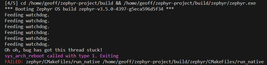
To disable the software watchdog at boot, you can add the following to your prf.conf:
CONFIG_WDT_DISABLE_AT_BOOT=yYou can initialize your software watchdog before you hit main() using Zephyr’s SYS_INIT() macro, which allows you to specify functions to be called at different stages of the kernel initialization process before main() is called. This can be useful if you can’t rely on main() being called in all failure cases.
SYS_INIT(initWatchdog, POST_KERNEL, CONFIG_KERNEL_INIT_PRIORITY_DEFAULT);where initWatchdog is your function that initializes the watchdog.
When running Zephyr on the native_sim board (Linux), a software watchdog timeout will cause the program to exit. If you have not overridden the default handler, the message sys_arch_reboot called with type 1. Exiting will be printed to the console (the same message as you get if you call sys_reboot(SYS_REBOOT_COLD) directly).
If you ever need to remove a channel, you can use task_wdt_delete():
int rc = task_wdt_delete(myChannelId);__ASSERT(rc == 0, "Failed to delete watchdog channel. task_wdt_delete() returned: %d.", rc);Removing a channel is useful if you want to be able to test the module the WDT channel is using. Tests will typically create/destroy the module object many times over to test it, and you will run into issues on successive runs of tests if they previous test does not clean up after itself.
Providing Your Own Watchdog Handler
When providing NULL as the second parameter to task_wdt_add(), Zephyr calls the system reset handler. Instead, you can provide you own handler to implement custom functionality. I prefer to provide my own handler, and generally have this handler log an error, wait for a period of time, and then reset the device.
Here is an example of a handler that logs an error, waits for 5 seconds, and then resets the device:
void watchdogTimeoutHandler(int channel_id, void *user_data){ LOG_ERR("Watchdog timeout occurred. channel_id: %d. Resetting MCU in 5s.", channel_id); log_panic(); // Without this the log message will not be printed as we are in interrupt context k_busy_wait(5*1e6); // 5 seconds in microseconds. Can't use k_sleep() as we are in interrupt context! sys_reboot(SYS_REBOOT_COLD);}Then later on:
int wdtChannelId = task_wdt_add(5000, watchdogTimeoutHandler, nullptr);__ASSERT(wdtChannelId >= 0, "Failed to add watchdog channel. task_wdt_add() returned %d.", wdtChannelId);Note that log_panic() needs to be called after the log message otherwise it will never be printed. The handler function gets called in a interrupt context and thus does not allow the logging thread to run. Another effect of being in an interrupt context is that you can’t use k_sleep() to implement the delay. Instead, you need to use a busy wait like k_busy_wait(); to implement the delay. If you try and use k_sleep() with asserts enabled you will get the following error:
ASSERTION FAIL [!arch_is_in_isr()] @ WEST_TOPDIR/external/zephyr/kernel/sched.c:1115Nordic nRF Watchdog Example Code
Below is example code showing how to initialize the hardware watchdog for Nordic nRF devices. Firstly, the following is added to your prf.conf:
# WDT#==============================================================================CONFIG_WATCHDOG=yCONFIG_WDT_DISABLE_AT_BOOT=yCONFIG_TASK_WDT=yCONFIG_TASK_WDT_MIN_TIMEOUT=5000CONFIG_TASK_WDT_CHANNELS=2And then in a .c file somewhere:
static struct device const * l_watchdog = DEVICE_DT_GET(DT_COMPAT_GET_ANY_STATUS_OKAY(nordic_nrf_wdt));
void initWatchdog(){    // Watchdog timer    if (!device_is_ready(l_watchdog))    {        LOG_ERR("Hardware watchdog %s is not ready.\n", l_watchdog->name);        l_watchdog = NULL;        __ASSERT_NO_MSG(0);    }
    struct wdt_timeout_cfg wdt_config;
    wdt_config.flags = WDT_FLAG_RESET_SOC;    wdt_config.window.min = 0U;    wdt_config.window.max = 5000U; // NOTE: Does not actually get used if initialized by board_watchdog.    wdt_config.callback = Bsp_HwWatchdogHandler;
    int hwWdtChannel = wdt_install_timeout(l_watchdog, &wdt_config);    if(hwWdtChannel == -EBUSY)    {        // This is ok, and not an error.        LOG_INF("hw_wdt already setup. Likely this was setup in the bootloader. %d", hwWdtChannel);        return;    }    else if (hwWdtChannel < 0)    {        LOG_ERR("hw_wdt install timeout failed: %d", hwWdtChannel);        __ASSERT_NO_MSG(0);    }
    int ret = wdt_setup(l_watchdog, WDT_OPT_PAUSE_HALTED_BY_DBG);    if(ret)    {        LOG_ERR("Failed to setup watchdog: %d", ret);        __ASSERT_NO_MSG(0);    }    // Let's do a test feed to make sure the watchdog is working    ret = wdt_feed(l_watchdog, 0);    if(ret)    {        LOG_ERR("Failed to feed watchdog: %d", ret);        __ASSERT_NO_MSG(0);    }
    LOG_INF("Watchdog initialized.");}
Footnotes
-
Zephyr. gpio.h File Reference [documentation]. Retrieved 2024-11-12, from https://docs.zephyrproject.org/apidoc/latest/drivers_2gpio_8h.html. ↩
-
GitHub. nrfconnect - sdk-zephyr/dts/bindings/i2c/nordic,nrf-twim.yaml [code]. Retrieved 2025-07-30, from https://github.com/nrfconnect/sdk-zephyr/blob/v2.7.99-ncs1/dts/bindings/i2c/nordic,nrf-twim.yaml. ↩
-
Zephyr (2024, Jul 20). Docs / Latest > OS Services > Storage > Non-Volatile Storage (NVS) [documentation]. Retrieved 2024-12-19, from https://docs.zephyrproject.org/latest/services/storage/nvs/nvs.html. ↩
-
Zephyr (2024, Jan 16). Kconfig Search - CONFIG_TASK_WDT_CHANNELS [documentation]. Zephyr Docs. Retrieved 2024-01-17, from https://docs.zephyrproject.org/latest/kconfig.html#CONFIG_TASK_WDT_CHANNELS. ↩