Bootloaders

A bootloader is a program in a computer’s memory that runs before the main application. In an embedded context, it is typically responsible for:
- Configuring basic hardware (most of the hardware configuration is left to the main application, the bootloader would typically just configure the clocks it needs and perhaps the watchdog)
- Loading the main app into memory if not already in the correct place for execution (e.g. from external flash into main memory)
- Verifying the integrity of the main app (e.g. using a checksum or hash)
- Executing the main app (typically by disabling interrupts and then executing a “jump” instruction which goes to a predefined memory address)
- Updating the main app (this is optional, and if this functionality is required, it may be included in the bootloader or in the application depending on the chosen topology).
They are commonly added to microcontrollers to update the main firmware application. Bootloaders will use a communication protocol/transport to “download” new firmware from a host computer (e.g. laptop via cable, or server on the internet). Common transports include UART, RS-232, I2C, CAN, Ethernet, WiFi or Bluetooth.
The bootloader will typically verify the downloaded image using a checksum or hash before allowing the new version of firmware to run. The bootloader can either then force a reset and boot into the new application, or allow it to happen at a more convenient time in the future. The bootloader can also enforce that the application “checks in” and states it’s ok (typically once initialization is complete) otherwise it will fall back to the previous version.
Bootloaders are typically the first thing that is run whenever the microcontroller is reset. This gives the bootloader control over what application to then boot.
Child Pages
Memory Layout
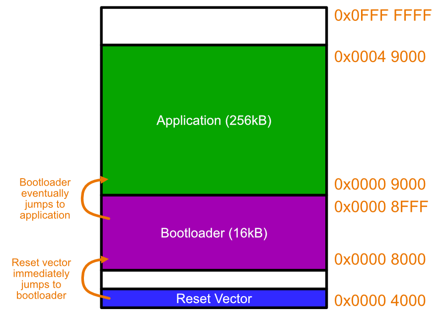
The image below shows what the memory layout might look like for a microcontroller using a basic bootloader. The Reset Vector is the first instruction executed by the microcontroller on start-up. This is typically located at memory address 0x0000 0000 (the Intel 8086 processor is a notable exception). The reset vector usually contains a “goto” (jump) instruction that tells the CPU to jump to the bootloader’s entry point. The bootloader will then execute. The bootloader could then initialise a transport to download new firmware, e.g. over UART. It then might wait for a message for a fixed amount of time. After 10s the chance to download firmware passes, and then the bootloader jumps to the start of the application executable.
Erase Cycles
Flash memory has a limited number of erase cycles, and you have to be careful you do not exceed this number during the lifetime of the device.
Typical erase cycle limits for NOR flash are 10k to 100k erases. This should not be a problem for most applications that only erase/write flash during a new version as part of the bootloader process. Be careful however if you are writing to flash during normal operation also, such as updating configuration data/settings that you want to persist across power-loss or reboots.
Multiple Application Images
Relocation can be problematic for memory. When your firmware application undergoes the linking step during compilation, the linker assigns memory addresses for all the functions and static variables in your code. It needs to know where the executable is being placed in memory to do this. But what if you have two different images, which require different offsets?
One solution is a swap algorithm.
Swap-Scratch Algorithm
The Swap-Scratch algorithm is a way of swapping two firmware images in flash memory.
The scratch area must be large enough to hold the largest sector that is going to be swapped.
Swap-Move Algorithm
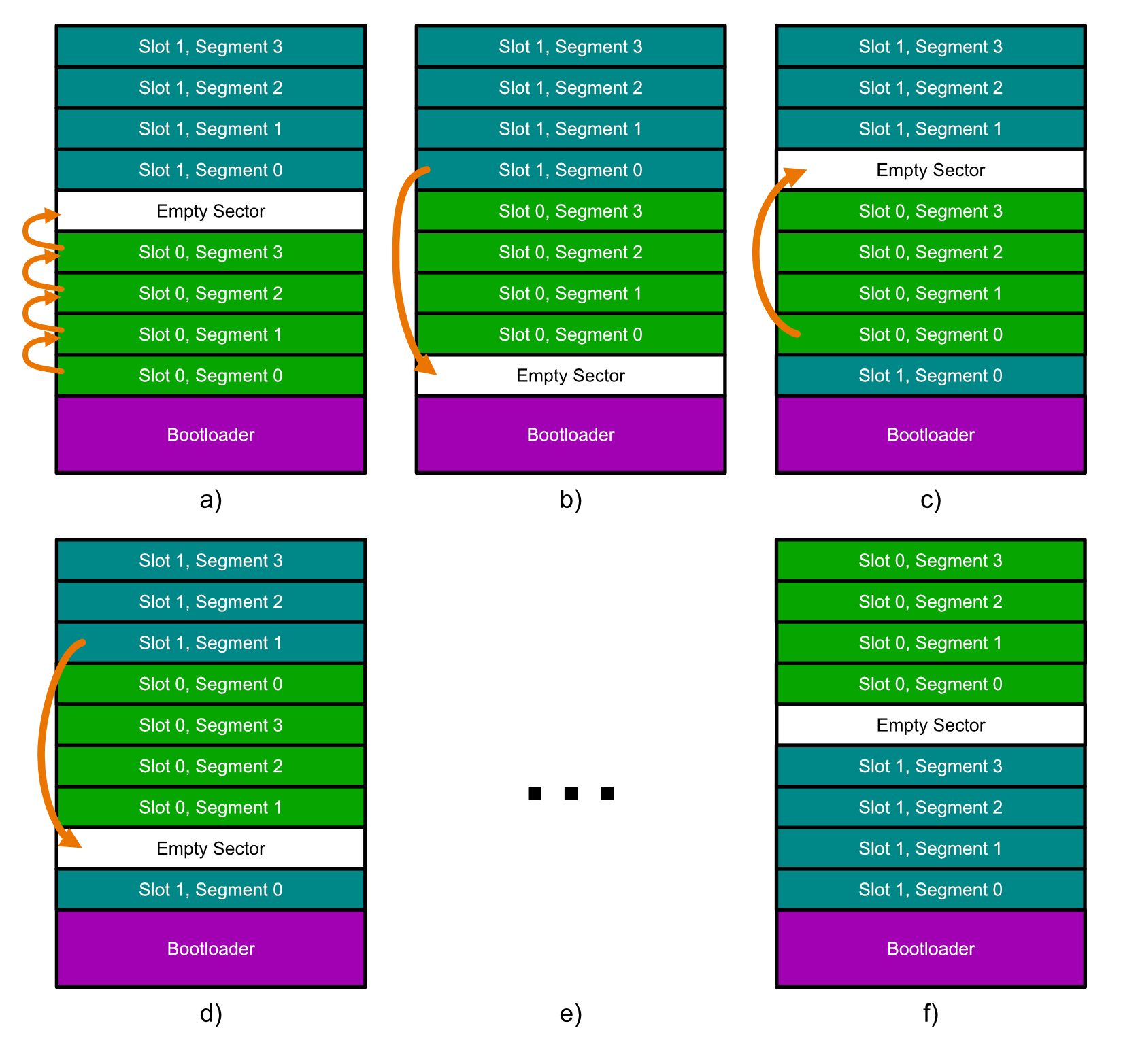
- a): All of the segments in slot 0 are moved one segment up, starting by copying segment 3 into the empty sector, then segment 2 into where segment 3 used to be, etc. This moves the empty segment to the start of slot 0.
- b): The first segment of slot 1 is moved down to the empty segment.
- c): The first segment of slot 0 is moved up to where the first segment of slot 1 used to be.
- d): The process repeats b) and c) now with the second segments of each slot.
- e): This continues until…
- f): All segments have been swapped over and the empty segment is back at the end of slot 0. Job done! Note that the contents of each slot have been swapped. I’ve kept the old names for each slot to highlight the fact they have moved. Technically speaking though, slot 0 is still in the same place, it just now has the contents of what used to be in slot 1.
Each segment in slot 0 is erased/written to twice and each segment in slot 1 is erased/written to once. This is a significant improvement over the Swap-Scratch algorithm which performs as many erase/write cycles as there are segments.
Security
TODO: Add info here.
Golden Image
A golden image is a firmware application with minimal support for firmware updating. If updating over-the-air (OTA), then this image must include basic wireless comms support. It is usually stored either in external flash or in a protected area of the microcontroller’s internal memory. It is loaded by the bootloader if the main application is faulty, and in that sense, it is a backup application which is guaranteed to work.
Overwriting Bootloaders
Typically, you design a bootloader and the start of a project and plan to never have to update it. But sometimes plans change (or bugs are found) and you will need to update the bootloader. You can usually do this by bootloading on a version of the application which includes code to update the bootloader (e.g. write to the bootloader’s memory space in flash to update it). You have to be careful when doing this, as if the bootloader update process gets interrupted or corrupted for any reason, you generally end up bricking your device.
You can bundle the bootloader code you want to write inside the application. In C/C++, this can be done by using objcopy to copy contents from a .bin file into a .o which can be linked into your application build process.
objcopy -I binary -B <architecture> -O elf32-little my_input.bin my_output.oWhen objcopy creates the .o file, it will automatically create three symbols your application can use to reference the data:
_binary_my_input_bin_start: The start address of the data in the binary file._binary_my_input_bin_end: The end address of the data in the binary file._binary_my_input_bin_size: The size of the data in the binary file.
Then, link this my_output.o file with the rest of your application during the build process. These special symbols can be used by declaring them as extern in your C/C++ code:
extern const unsigned char _binary_my_input_bin_start[];extern const unsigned char _binary_my_input_bin_end[];extern const unsigned int _binary_my_input_bin_size;
void access_binary_data(void) {    const unsigned char* start_ptr = _binary_my_input_bin_start;    const unsigned char* end_ptr = _binary_my_input_bin_end;    unsigned int size = _binary_my_input_bin_size;
    // Use the data (e.g., iterate from start_ptr to end_ptr)    // ...}
Enabling Watchdogs
It is good practice to enable the hardware watchdog as soon as possible in the MCU boot process, which means early in the bootloader. If you wait until the application starts before enabling the watchdog, you might get occasionally stuck in the bootloader with no automatic ability to reset. When passing of control from the bootloader to the application, the watchdog remains active. Design your timeouts so that it gives the application enough time to initialize and start feeding the watchdog so you don’t inadvertently reset during the transition process. Luckily, jumping to the application is usually quick, as it typically involves disabling interrupts and then executing a “jump” instruction to the start of the application.
Zynq 7000 Boot Sequence
BootROM is the first thing that executes. BootROM runs on the first A9 processor core on the Zynq. The second A9 executes a “wait for event” (WFE) instruction.1
The main job of BootROM is to configure the system, copy the First Stage Bootloader (FSBL) from the boot device (e.g. QSPI flash) to the on-chip memory (OCM) and then execute the FSBL.
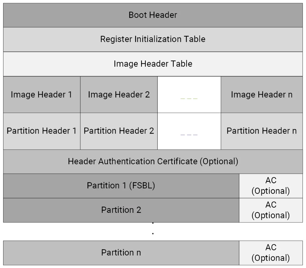
The BootROM expects the boot images to be in a specific format as defined by AMD. Each boot image contains:
- A boot header. This contains info such as whether the boot image is encrypted, the size, offset and execution address of the FSBL, and offsets to the image and partition header tables.
- A register initialization table: This contains 256 address-value pairs used to initialize PS registers for MIO multiplexing, and flash clocks.1
- An image header table.
- Image and partition headers.
- Partition 1 containing the FSBL.
- Optional additional partitions containing the main application.
Confusingly, AMD uses an “image” to refer to two different things. A “boot image” is the entire structure defined above. This “boot image” can contain multiple images, which are defined as pieces of data that have been extracted by Bootgen from files (e.g. the ELF files, bitstream, data files) when creating the boot image. For example, the FSBL is an image, as is the main application1. Each image inside the overall boot image can contain one or more partitions. One use case for this is because an ELF file can contain multiple loadable sections — each one of these sections becomes a partition.
There is a method for the FSBL (or other applications running post-BootROM) to make the BootROM boot a different boot image. This is done by the FSBL writing to devcfg.MULTIBOOT_ADDR and then performing a software system reset.2 This is useful for example if the FSBL detects that the main application is corrupt and there is a secondary/backup boot image available (or rollback to a previously stable version).
Bootloader Libraries
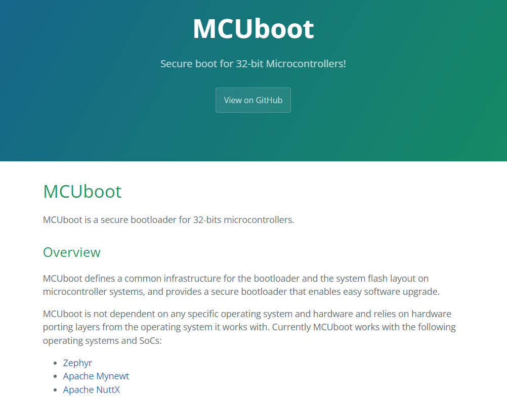
MCUboot
MCUboot is a popular, open-source, secure bootloader for 32-bit microcontrollers. As of Jan 2024 it has 1.1k stars on GitHub, 2,201 commits and active development month over month. It is designed to be run from flash memory3.
It currently supports the following frameworks/OSes:
- Zephyr
- Apache Mynewt
- Apache NuttX
- RIOT
- Mbed OS
- Espressif
- Cypress/Infineon
- Simulator (primarily for testing the upgrade code and badly timed resets - written in Rust4)
The MCUboot implementation for Zephyr supports Bluetooth bootloading. The Nordic nRF app can be used to bootload during development.
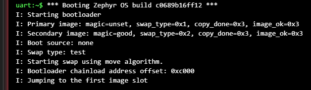
On start-up, MCUboot inspects the images in each of the slots to work out what type of swap to perform (if any). It decides to do one of the following:5
BOOT_SWAP_TYPE_NONE: This is the usual or “no upgrade” process, in which MCUboot boots the primary image.BOOT_SWAP_TYPE_TEST: Swaps the images and then boots the new primary image, but reverts back to the old image on the next reset. This will involve MCUboot swapping back the images on the next reset.BOOT_SWAP_TYPE_PERM: Swaps the images and then boots the new primary image.BOOT_SWAP_TYPE_REVERT: A previous test swap was not made permanent.BOOT_SWAP_TYPE_FAIL: The swap failed.BOOT_SWAP_TYPE_PANIC: An unrecoverable error occurred while swapping.
Magic Number
MCUboot uses a magic number to detect whether or not a slot contains a valid image. The magic number is long and random enough that it is statistically very unlikely to be present in memory unless it was purposely written. The magic number is written to the last 16 bytes of each image slot.
Footnotes
-
AMD. UG1283 - Bootgen User Guide. Retrieved 2024-08-16, from https://docs.amd.com/r/2023.1-English/ug1283-bootgen-user-guide/Introduction. ↩ ↩2 ↩3 ↩4
-
AMD (2023, Jun 30). UG585 - Zynq 7000 SoC Technical Reference Manual. Retrieved 2024-08-16, from https://docs.amd.com/r/en-US/ug585-zynq-7000-SoC-TRM/Zynq-7000-SoC-Technical-Reference-Manual. ↩
-
MCUboot. MCUboot - Secure boot for 32-bit Microcontrollers! [project homepage]. Retrieved 2024-01-27, from https://docs.mcuboot.com/. ↩
-
MCUboot. MCUboot simulator - README. Retrieved 2024-01-27, from https://github.com/mcu-tools/mcuboot/blob/main/sim/README.rst. ↩
-
MCUboot. MCUboot - Design [documentation]. Retrieved 2025-08-28, from https://docs.mcuboot.com/design.html. ↩