Test Jigs

Test jigs are production-line devices used to both program and test PCBs. This page focuses on the design of test jigs used to test assembled PCBs (PCBAs) that have not yet been fitted into the product (or if they have, the PCBA’s surface is still available for pogo pin connections).
Pogo Pins
Most test jigs use pogo pins (spring loaded connectors) to make electrical contact in many places with the PCB during testing. This saves the need for plugging in traditional connectors, which are slower, more expensive (as the PCB needs a mating connector) and take up more space on the PCB.
Small surface mount pads can be added to the PCB where you want the pogo pins to make contact. For high current applications, you can either use:
- More pogo pins in parallel
- Larger pogo pins
- Traditional wire-to-board connectors (although this slows down production, it might be a must if pogo pins are just not sufficient).
Pogo pin tips are available in a range of shapes, including rounded, single-point, and multi-point. I have seen issues with rounded pogo pin tips and bad electrical contact with the PCB. I assume it was either due to residual flux on the PCB or oxidation of the tip or PCB pad, combined with the rounded tip, meaning poor electrical contact was made. For this reason I recommend using the pointed style tips (which I’m assuming can “pierce” through the flux or oxidation) and ones with a strong spring force.
Another point worth considering when using pogo pins is that you will not be testing the connectors on the PCBA. In most cases this is not a big issue since connectors are typically not parts which are faulty, and testing the connectors means you can’t just rely on pogo pins and need to plug into these connectors, drastically slowing down the testing process.
Software
You typically need to control the test jig to perform the testing. While you could use a microcontroller to do this, it is generally a better idea to use an operating system such as Windows or Linux. This allows you to easily develop the software in a language such as Python, connect to external databases to record the results, and use a variety of tools to help you debug and test the software. If parts of the testing require real-time control that a general purpose OS is not capable of, you can complement the OS with a microcontroller to do the real time aspects.
Python is a great language for this as it’s quick to write, has a large library of tools for interfacing with embedded devices (e.g. serial ports, programmers, I/O boards, etc.) and is easy to debug.
You might be tempted to use a unit test library to structure the software. However, unit test software is designed to run small tests that are independent and isolated from each other. This does not fit end-of-production line testing, as many of the tests require strict ordering and depend on other tests passing. For example, you can’t really test much prior to programming the device. Then configuration and other communication may have to occur before the main tests.
Test Functions
Write each test as its own function. This allows you to write a generic def run_test(test_function) function that can perform common tasks prior to and just after running each test step (such as checking whether the test passed or failed, logging the result, and measuring the time taken to run the test). This also allows you to restructure the ordering of the tests easily or make different combinations of test steps into different complete test sequences.
Test Functions as a List
An easy way to run the tests is to gather them into a List and then loop through them to run, as shown below:
list_of_tests = [    test_program_device,    test_connect_via_serial,    test_configure_device,    test_check_temperature,    test_write_serial_number,    test_save_results_to_database,]
# Then....for test in list_of_tests:    test()
This works well if you have a fixed set of tests that are always run in the same order, and there typically is no conditional logic to the running of the tests.
Creating a Test Step Class
You may want to create a TestStep class which can hold a bit more information about each test step, rather than just the function to call. This extra data could include the name of the test step and the number of attempts to try before giving up.
class TestStep: def __init__(self, name: str, function: Callable, max_attempts: int = 1): self.name = name self.function = function self.max_attempts = max_attemptsThen you could build up a list of test steps and then loop through them to run, like this:
# Your test steps are defined here...test_steps = [    TestStep("Program Device", test_program_device, max_attempts=3),    TestStep("Connect via Serial", test_connect_via_serial, max_attempts=2),    TestStep("Configure Device", test_configure_device, max_attempts=2),    TestStep("Check Temperature", test_check_temperature, max_attempts=1),    TestStep("Write Serial Number", test_write_serial_number, max_attempts=2),    TestStep("Save Results to Database", test_save_results_to_database, max_attempts=1),]
# Then when you want to run the tests:for test_step in test_steps:    for attempt in range(test_step.max_attempts):        try:            test_step.function()            logger.info(f"Test step {test_step.name} passed on attempt {attempt + 1}")            break        except Exception as e:            logger.warning(f"Test step {test_step.name} did not pass on attempt {attempt + 1}: {e}")            if attempt == test_step.max_attempts - 1:                logger.error(f"Test step {test_step.name} exhausted all attempts ({attempt + 1}). Failing the test.")
Conditional Logic
If you need to run tests conditionally or in different orders that depend on runtime conditions (e.g. you may only want to run the test_configure_device test if you detect during the connection test that it is not already configured), the list based approach above will not work well. A better approach in this case is to just call the test functions from a “parent” test sequence function. You may also want to make a wrapper function that can be called from the parent to run each test, so as to re-use some common logic like catching exceptions from the test function and treating that as a failure.
def run_tests(): run_test(test_program_device) run_test(test_connect_via_serial) run_test(test_configure_device) run_test(test_check_temperature) run_test(test_write_serial_number) run_test(test_save_results_to_database)Log Everything
The number of failure modes when doing production line testing can be quite high, and the modes themselves hard to predict. For this reason, it is important to log everything. This gives the tester the best ability to diagnose, categorise and fix the problem (the fixing may occur later by someone else, or not at all if the cost to repair is too high compared to the cost of the device).
If writing the software in Python, you can use the built-in logging library (import logging) to log messages. You can setup a handler on the root logger (child log messages will propagate up to the root logger and also be emitted by the handler) to format the logs in your desired way.
import loggingimport colorlog
# Setup root logger, all child loggers will propagate up to the root logger and be emitted by the handler attached to this.root_logger = logging.getLogger()root_logger.setLevel(logging.INFO)
# Create a colored stream handlerhandler = colorlog.StreamHandler()
# Configure the formatter with colors# Orange for warnings, red for errorsformatter = colorlog.ColoredFormatter(    '%(log_color)s%(asctime)s - %(levelname)s - %(name)s:%(lineno)d - %(message)s',    log_colors={        'DEBUG': 'cyan',        'INFO': 'white',        'WARNING': 'yellow',  # Yellow/orange for warnings        'ERROR': 'red',       # Red for errors        'CRITICAL': 'red,bg_white',    })
handler.setFormatter(formatter)root_logger.addHandler(handler)
Then in other files:
import logging
logger = logging.getLogger(__name__)
def test_program_device():    logger.info("Programming device...")
    try:        # Call programming function        test_result = programming_function()        logger.info("Device programmed successfully")    except Exception as e:        logger.error(f"Device programming failed: {e}")        return False
    return True
Save Test Results to a Database
The best way to troubleshoot the test process is to build up a database of test results and analytics.
It can be as simple as writing to a local CSV/JSON file, or saving to a cloud-hosted database. Cloud hosted databases are not that hard to set up these days (especially with AI help), so I would recommend doing that unless you have a strong reason to keep it local (perhaps SQLite could be a good option if you want to keep it local, but a little more organized than just dumping to text).
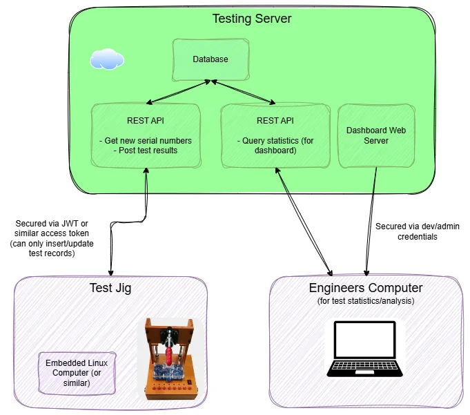
Using a database (like PostgreSQL) also allows you to easily query the data later from another location, and makes it easy to support multiple test jigs. Permissions on the database can be locked down to only allow the test jig to insert or update records (update is needed if you want to re-run devices through the test jig and update the provisioned device record, this can be sometimes combined into a single UPSERT operation).
If using a database, I would recommend having at least two tables: one for the test attempts and one for the provisioned devices (devices which pass all the tests and are good to go in production).
Here is an example of what your test attempt table columns might look like (customize as you see fit for your needs):
id: Unique incrementing integer that can identify a test attempt.serial_number: The serial number of the device being tested. This could be any form of unique identifier, such as a MAC address, MCU serial number, or one programmed onto the device yourself.test_result: EitherPASSEDorFAILED.test_steps: A JSON array of the steps that were taken during the test. Because each test step could contain arbitrary data, it’s usually better to not structure this data and just accept JSON. Each test step could contain information such as a unique name (e.g.CHECK_TEMPERATURE) and a short message (e.g."Read back temperature of 25.3°C. Lower limit: 24.0°C, Upper limit: 26.0°C.").tester_id: The unique identifier of the test jig that was used to test the device. Typically read from a config file by the test jig software.timestamp: The timestamp of the test attempt.logs: A JSON array of the logs from the test attempt. You may only want to save the logs if the test failed as the logs are usually quite verbose and could quickly consume your storage space.
Only devices which pass all the tests are added to the provisioned devices table. The columns in the provisioned devices table are:
id: Unique incrementing integer that can identify a provisioned device.serial_number: The serial number of the device being tested. This could be any form of unique identifier, such as a MAC address, MCU serial number, or one programmed onto the device yourself.pcb_version: The version of the PCB that was tested.firmware_version: The version of the firmware that was programmed onto the device (if applicable). For more complex devices, there may be multiple firmware versions (e.g. bootloader, application, multiple MCUs, etc.). I would recommend storing each one as a separate column.tester_id: The unique identifier of the test jig that was used to test the device. Typically read from a config file by the test jig software.created: The timestamp of the creation of the provisioned device record.last_updated: The timestamp of the last update to the provisioned device record.
Note that while the test jig only needs to insert new records into the test attempt table, it usually needs to be able to insert and update (or just “upsert”) records into the provisioned devices table. This is because the same device may be tested multiple times, e.g.:
- During development, you will be writing the Python code and running the tests again and again on the same device
- During production, you may want to test a previously provisioned device if you change something, improve a test, or are just not sure about its testing state.
Assigning Unique Serial Numbers
PostgreSQL databases have a special object called a “sequence” that can be used to generate unique serial numbers. A sequence is a database object that generates unique numerical values, even when accessed concurrently from multiple connections (they are typically used to generate a unique identifier for a primary key in a table). This makes it easy to generate a serial number without having to implement locking and concurrency control in the database API yourself.
Test Step Parallelism
If your test steps take a significant amount of time, you may want to consider running some of them in parallel. Obviously this would only apply to test steps that are independent of each other (e.g. a test step that needs to reset the MCU cannot really be run at the same time as a test step that needs to communicate with it).
Test step parallelism can be achieved using the built-in threading library in Python (or asyncio if you are using that style of asynchronous programming). Note that Python threads are not true parallelism due to the GIL (Global Interpreter Lock), but they are fine for this use case because the test steps are typically IO bound, not CPU bound.
If you are providing the tester with a command-line interface, watch out for threads messing up with Ctrl-C (terminate the program) behaviour. Ctrl-C is only caught in the main thread, and if you have other threads currently running parallel test steps, the program will not exit as expected. Two options to fix this are:
- Make the worker threads daemon threads, so that they are automatically terminated when the main thread exits.
- Catch the Ctrl-C signal in the main thread and then use a
threading.Eventto signal to the worker threads to exit. You have to make sure the worker threads periodically check the event and exit if it is signaled.
Analytics
One of the most commonly used test metrics in industrial test monitoring is the First Pass Yield (FPY). This is the percentage of devices that pass all the tests on the first attempt. It is a simple metric to calculate and can be used to track the quality of the test process over time.
Another interesting metric is the Process Capability Index (Cpk). This is a measure of how well a measured parameter’s distribution (both its spread and centring) fits within its specification limits.
Both of these metrics are easy to calculate if you are saving test data to a database.
The following metrics can be useful on a testing dashboard. All are captured within a user selectable time window so that you can see how things are trending over time.
Summaries:
- FPY (first pass yield).
- Failures by test step.
It’s also important to be able to drill down into individual tests if needed. A page dedicated to showing individual test runs (a table where each row is a test run, latest first, paginated to 50 or so at once) works well. Provide inputs to filter tests by failing or passing, start and end date ranges, test step name etc.
Clicking on a test run in the table should take you to a page with data on that specific test (e.g. pass/fail, run time, captured log output).
Debugging at Production Time
Test jigs are commonly sent to the factory that is assembling the PCBs so that they can be tested at the same place they are assembled. This saves time and money if there are production problems by catching them early. This also allows the PCB to be directly installed into the product assuming it passes the tests.
Always consider how you are going to inspect and fix issues with the test fixture at production time. I recommend connecting the test jig to the internet via Ethernet cable (more reliable than WiFi, and does not require authentication) assuming the factory will allow this (any competent factory will be able to sandbox your test jig so it has access to the internet via an Ethernet cable into their switch/router, but not the rest of the factory’s network).
If you can rely on having an internet connection, then SSH and desktop sharing software are two great tools to debug and diagnose issues with the test jig at production time.
Creating a testing dashboard (assuming you have a testing server) that can display test results and aggregate statistics is a really useful tool for improving the production process.
The Great Chinese Firewall
If the test jig is going to be deployed in China, you will need to consider the Great Chinese Firewall. This usually blocks or throttles VPN protocols and SSH connections to foreign hosts (whilst generally allowing ordinary HTTPS traffic through). This means things like VPNs and being able to SSH into the test jig are not normally possible. Tunnels and reverse proxies (where the test jig reaches out to a server, and you connect to the test fixture by also reaching out to the server) are not likely to work either. Cloud services like AWS, Azure, and Google Cloud are usually blocked (important if you were planning on hosting a test jig database on one of those). However these services can offer China regions which do work (and sometimes replication from within China region to outside) — with the caveat that they normally require different accounts to the rest of the world.
The firewall can prevent your test jig from connecting to the testing database (assuming you have one). One solution to this is to put a HTTPS REST API server in front of the database so that the test jig can connect to the API server instead. The firewall usually lets through this traffic (even though it’s HTTPS, i.e. encrypted). This has the added benefit of giving you greater control over data access and security, at the expense of extra complexity (now you have to manage the API server and keep it up to date with the database schema).
Certificates
Sometimes the device you are testing will require a certificate and/or key to be programmed onto it. This is usually for authentication so that other services (such as a cloud server) can authenticate the device at runtime.
You can have the test jig generate the certificates, but this means storing the intermediate signing key on the test jig itself. This could be a security concern depending on where the test jig is being physically used. One alternative is to add a certificate signing API to the test jig server. That way the test jig does not need to hold the signing key. Instead, it sends a certificate signing request (CSR) to the test jig server with the relevant DUT information. The server has the intermediate signing key and creates the device certificate and key. These are sent back to the test jig which then programs them onto the device.
OpenHTF and TofuPilot
OpenHTF (Open Hardware Testing Framework) is an open-source Python framework for testing hardware. It was originally developed at Google.1 It provides a framework for structuring tests into Phases and running them in sequence.
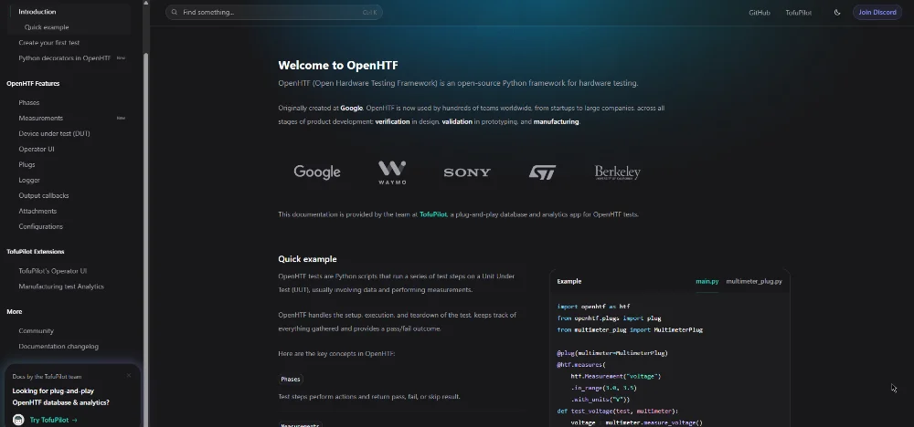
TofuPilot is a commercial offering built on top of OpenHTF which provides web-based databases and dashboards for logging and analysing test results. It has tight integration with OpenHTF, although it supports other test frameworks such as pytest and custom test functions.2
Suppliers
Redback Test Services
An Australia-based company that designs and manufactures test jigs.
INGUN
A German manufacturer of test fixtures and test probes. For example, see this video of their Manual Test Fixture MA 160: https://www.youtube.com/watch?v=NeKGzh2sa1k.
Footnotes
-
OpenHTF. OpenHTF - Homepage [website]. Retrieved 2026-03-24, from https://www.openhtf.com/. ↩ ↩2
-
TofuPilot. TofuPilot - Homepage [website]. Retrieved 2026-03-24, from https://www.tofupilot.com/. ↩