PCB Data Formats
PCB data formats are used to convey PCB manufacturing and assembling information from the designer using CAD software to the company(s) making the PCB.
There are few different types of formats which are explained in more detail below.
Gerber Files
Overview
Gerbers are files which hold PCB design information. It is an old format, first developed in 1980, but as of 2020 is still the most commonly accepted format for providing PCB design information to PCB manufacturers for both PCB creation and assembly. A CAD program used to design PCBs will normally output a set of Gerber files (e.g. one for each copper layer, silkscreen layer, soldermask layer, solder paste layer, mechanical layer and one for component placement of each side of the PCB).
A Gerber file has no information about the number or names of electrical nets. It also does not include orientation information, which puts the onous on the PCB assembler to determine this, which can be especially difficult for polarity-sensitive packages and the variety of different styles for indicating polarity (silkscreen dots for pin 1, thicker silkscreen lines for cathodes, different copper pad shapes for pin 1, e.t.c)
Versions
There are two versions of the Gerber format:
- Standard Gerber (RS-274-D)
- Extended Gerber (RS-274X)
Extended Gerber is the most common Gerber format, the standard Gerber format is depreciated.
Layers
Layers are sorted alphabetically by extension.
| Extension | Layer Name | Description |
|---|---|---|
| .GBL | Bottom Layer | The bottom copper layer. |
| .GBO | Bottom Overlay (Silkscreen) | |
| .GBP | Bottom Paste | |
| .GBS | Bottom Soldermask | |
| .GKO | Keep Out Layer | |
| .GMx | Mechanical Layer x (x is normally 1-16) | |
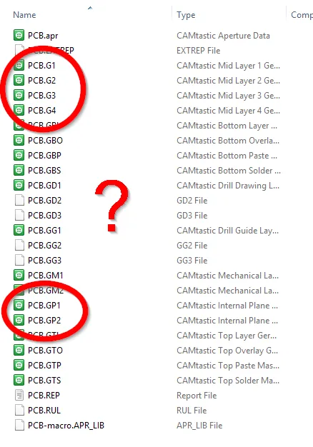
| .GPx | Inner Plane Layer X | These are negative layers, where there are objects on this layer is where there will not be copper on the final PCB. |
| .GPB | Bottom Pad Master | Includes only the copper pads on the bottom layer, it removes all vias, tracks, fills and arcs. |
| .GPT | Top Pad Master | Includes only the copper pads on the top layer, it removes all vias, tracks, fills and arcs. |
| .GTL | Top Layer | The top copper layer. |
| .GTO | Top Overlay (Silkscreen) | |
| .GTP | Top Paste | |
| .GTS | Top Soldermask | |
| .GTS | Top Soldermask |
Notice how the top and bottom pad master file extensions do not follow the same format as the other “Top” and “Bottom” classed files, with their extensions being GPT/GPB rather than GTP/GBP.
Gerber File Viewers
Altium loads up Camtastic (which comes installed with Altium) whenever you generate Gerbers with the “Open Output” option ticked.
Disadvantages
The Gerber file format has long been criticized for it’s inability to accurately represent all of the PCB information required by the manufacturer and/or assembler. A typical example would be sending the PCB layer information in Gerber files, the drill file in Excellon format, notes for the PCB either added as text to a Gerber layer or in a Word document, the BOM in an Excel file, and schematics (if needed) in a PDF. This has led to the design of new PCB data file formats.
For anything greater than a 2 layer board, the PCB manufacturer can have trouble distinguishing the layer order from the Gerber files. This is because the inner copper layers and plane layers are numbered separately (both starting from 1), and therefore the order in which they should be in is ambiguous.

ODB++
ODB++ is a database format originally developed by Valor to convey all the PCB information in a single file. ODB++ is now a format proprietary to Mentor Graphics who acquired Valor.
As of 2014, about 10% of all PCB designs are submitted in ODB++ format. It would be the second most popular choice after the Gerber format.
IPC-2581B
IPC-2581 is a new XML-based PCB data file format.
The standard is freely downloadable from IPC’s website.

