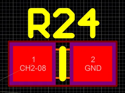
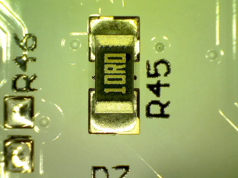
Designators
Designators are small component-identifying pieces of text that usually reside on both the circuit schematics and the top and bottom silkscreen layers of a PCB design.
For more information on what designators are used for what components, see the Component Schematic Symbols and Designators page.
Designator Placement On The PCB
Designators normally only face in two directions only (i.e. down-facing and right-facing).
If you cannot fit the designators next to their relevant components (e.g. a dense PCB), you can place a group of designators beside their components with the same orientation/placement, and the user can still understand which designator belongs to which component. You can see this being done on PC components such as motherboards and GPUs.

Resetting Designators
It is common practice to add and remove components to a PCB design half-way through the PCB component placement and routing process. You may add another resistor, R112, which needs to sit right next to R3 and R4. At this point, you may be tempted to reset all the designators so that R112 becomes R5.
However, there are pros and cons to resetting the designators on a PCB:
PROS
- You get to re-order the designators, this is especially true if there are now “gaps” (e.g. R8 and R10 exist, but there is no R9) after component changes have been made.
CONS
- Component numbers may no longer match up between versions (assuming a previous version of this PCB exists). This can be confusing when people refer to a component as “U7” on one version, but it is “U4” on the next.
- Changing designator text lengths may cause silkscreen violations on PCB. For example, if the designator used to be “C96”, and is renamed to “C102”, it will now be longer and may, say, run into a copper pad on the PCB.
- Component targeted rules and other design methodologies may stop working correctly if the CAD package uses the designators to identify the component. This is true with Altium when defining classes and rules based of the designators.


