Electric Skateboard Design
The Skateboard That Started It All…
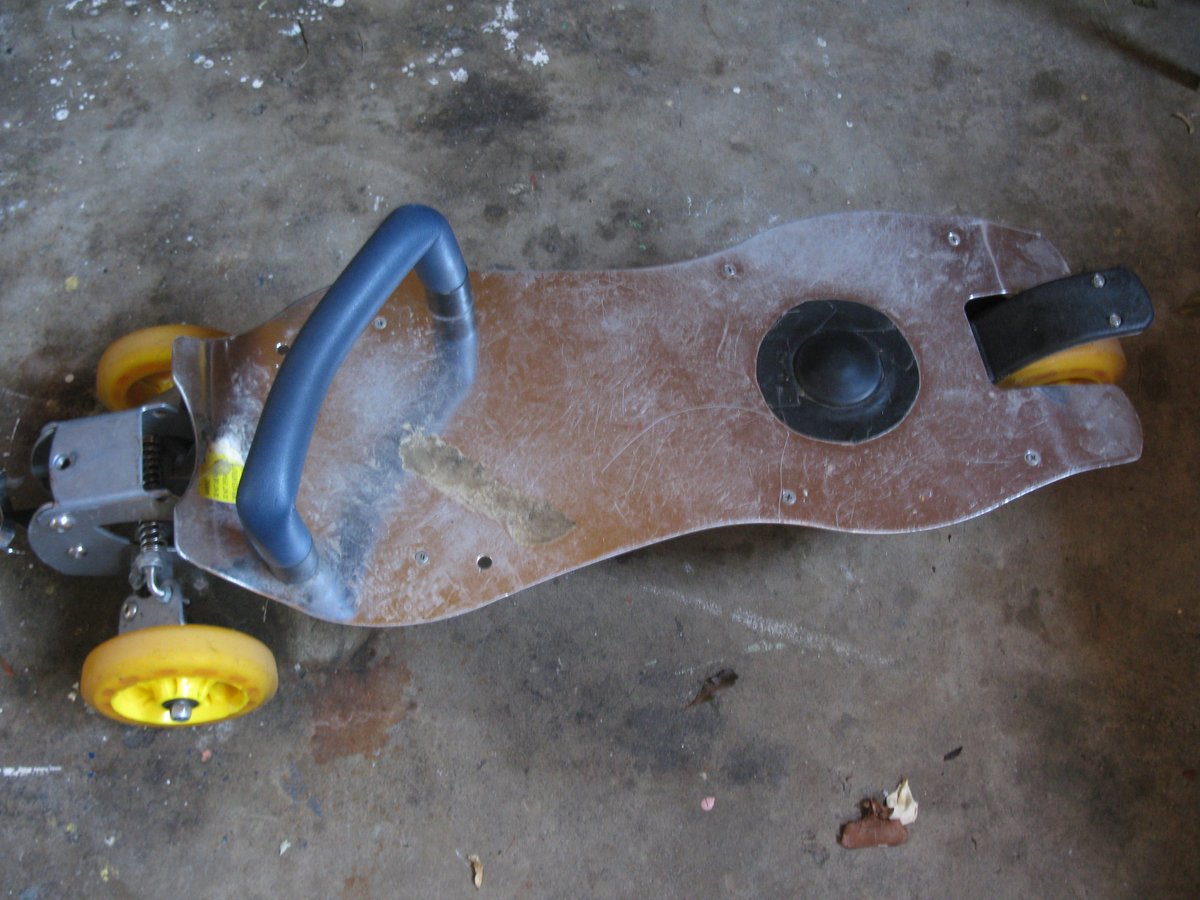
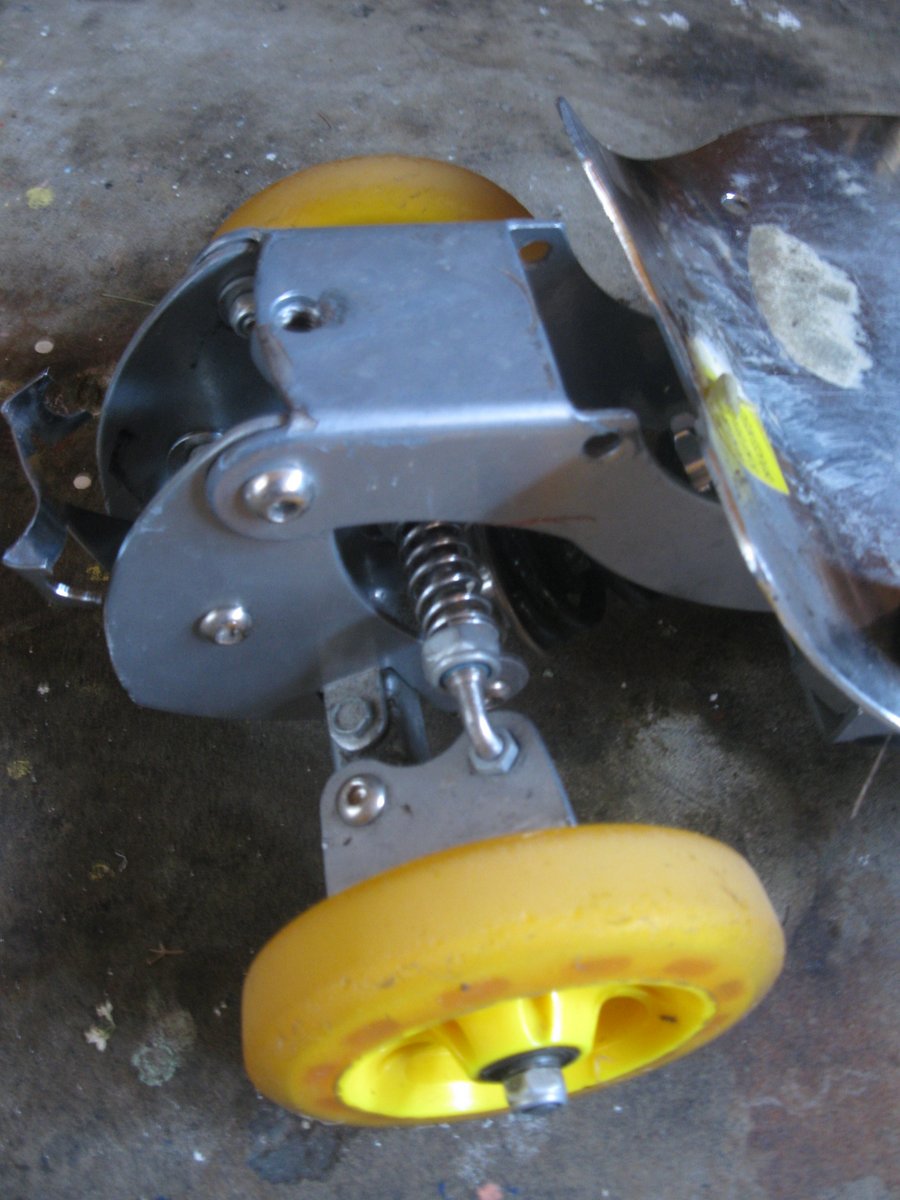
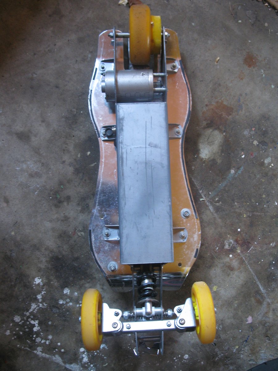
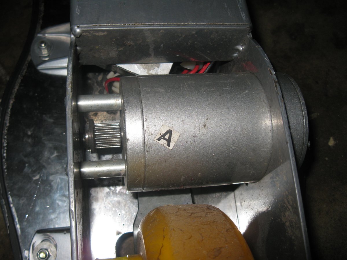
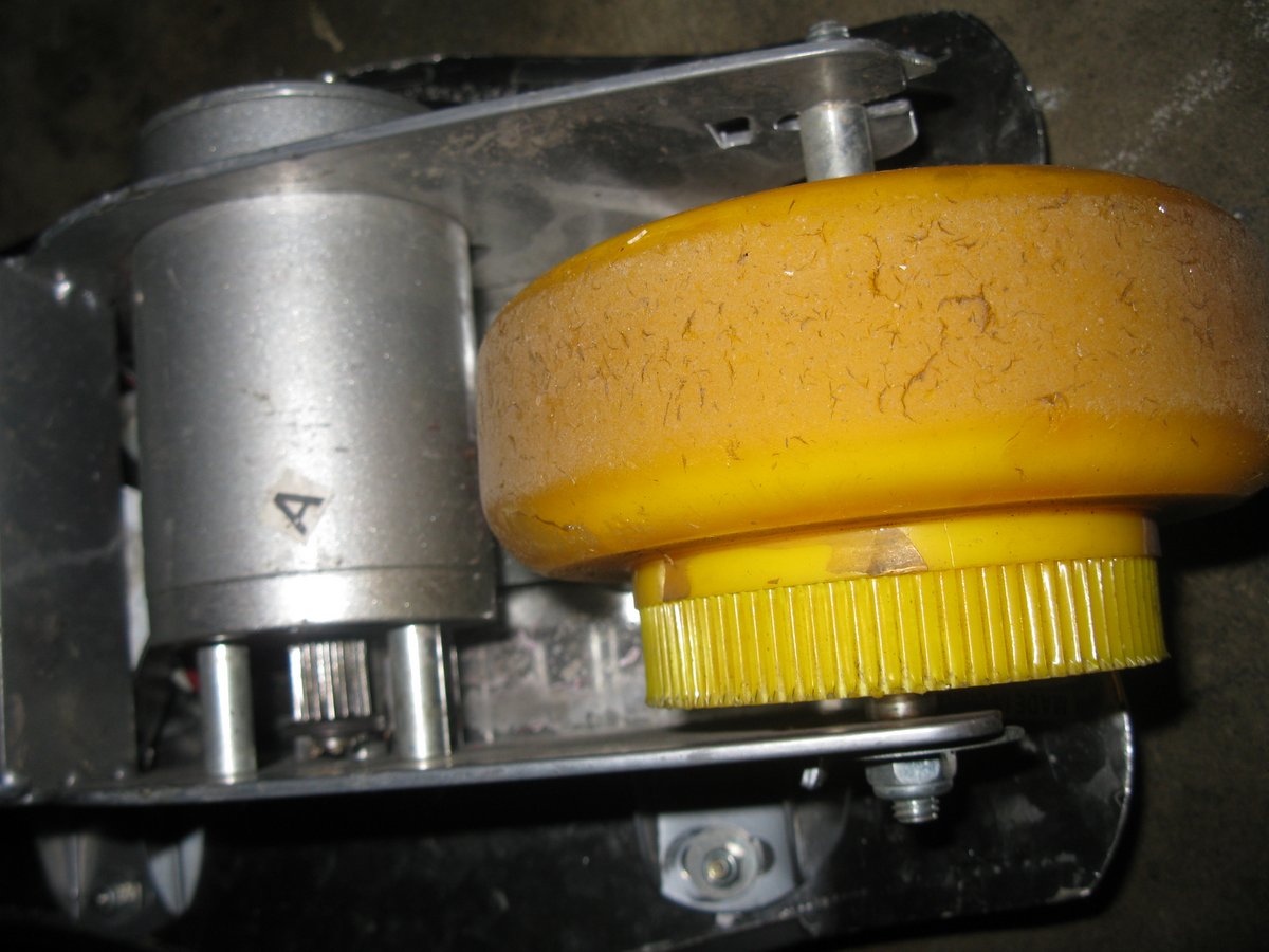
I brought this electric skateboard of a friend for NZ$20. This is what started my craze to build something better, faster, harder, stronger (did I get that in the right order?). This board comes fitted with a 120W brushed DC motor, which does get you places, but not quickly. It is powered by two 12V lead-acid batteries, which make it quite heavy. I managed to get about 5-6km from this board before it would crap out, leaving me to drag the thing the rest of the way home. Admittedly, the batteries weren’t in the best of condition, being many years old and having no charge/discharge activity in a long time. It’s operated by pressing down on a big button with your foot on the top of the board (it has one speed and one speed only).
Finding A Motor
The first thing to do was to find a new motor. The motor could possibly be the single most important part of the skateboard design. The motor is one of the primary factors in deciding how fast the board will go, the amount of power drawn from the battery, the acceleration/deceleration, and the ability to climb up hills (essentially the torque).
A skateboard requires a fairly powerful motor (in a non-commercial sense). The NZ$20 second-hand el-cheapo china skateboard mentioned above barely made it to 20km/h after 10 seconds at full throttle. Some of the more powerful commercial ones have a 500-800W motor on-board. Every single board I saw used a brushed DC motor (BDC). These are simple to control, but wear out faster and more importantly have a small power-to-weight ratio.
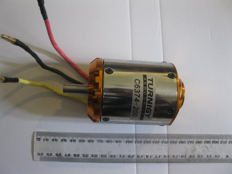
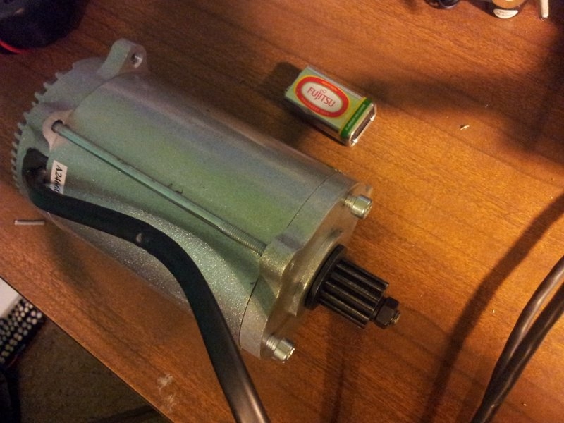
I decided to use the brushless DC (BLDC) motor shown above. BLDC motors have an awesome power-to-weight ratio and high efficiency (90%+), which will extend the distance the board can travel. This is at the expensive of being slightly harder to control (see the page BLDC Motor Control for more on that).
The ESC
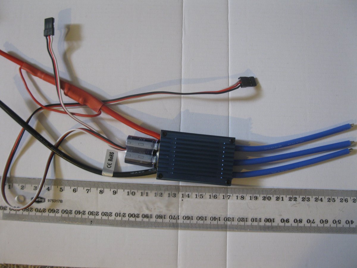
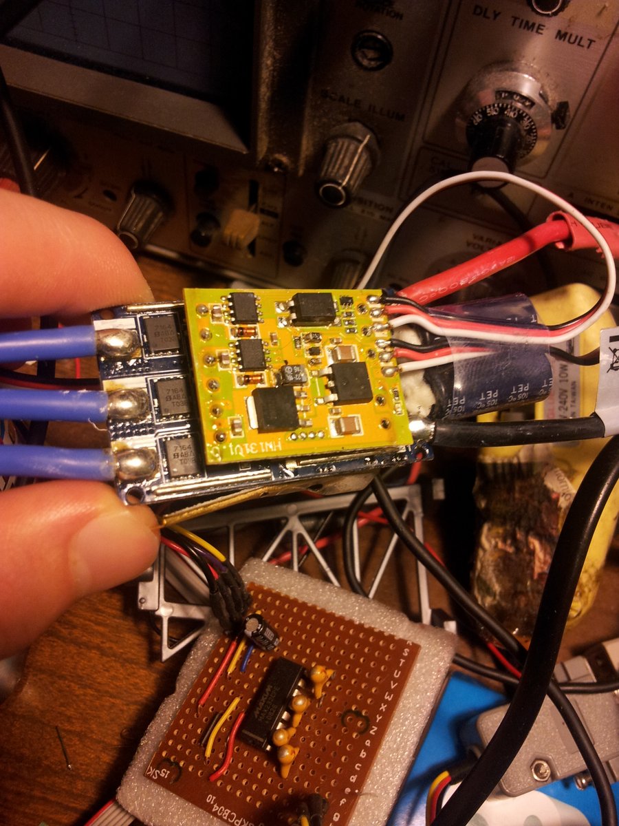
Designing a control system for a BLDC motor is not trivial, so I decided to use an off-the-shelf ESC (electronic speed controller).
Battery
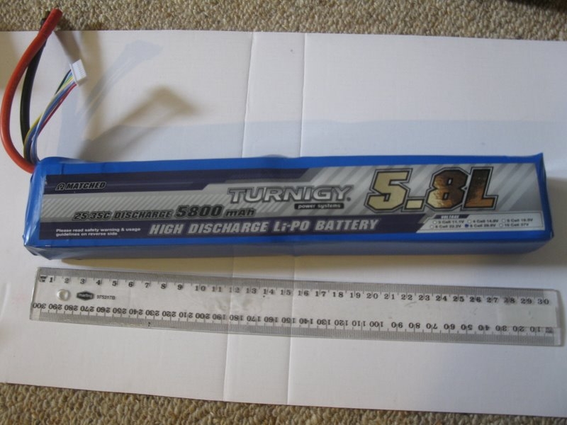
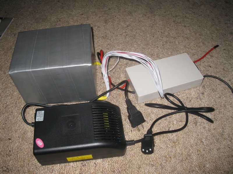
I decided to get a 29.6V, 5800mAh Li-Po (full details on the Hardware page). This gives it 171.68Wh’s of energy (it can supply 172W for 1 hour, or 343W for 30mins e.t.c).
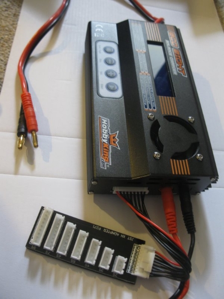
I also got this multi-chemistry battery charger shown below to charge it.
Wheels And Axles
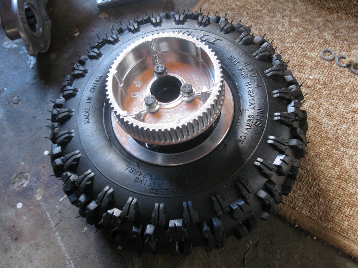
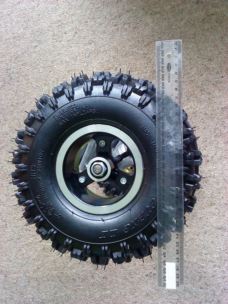
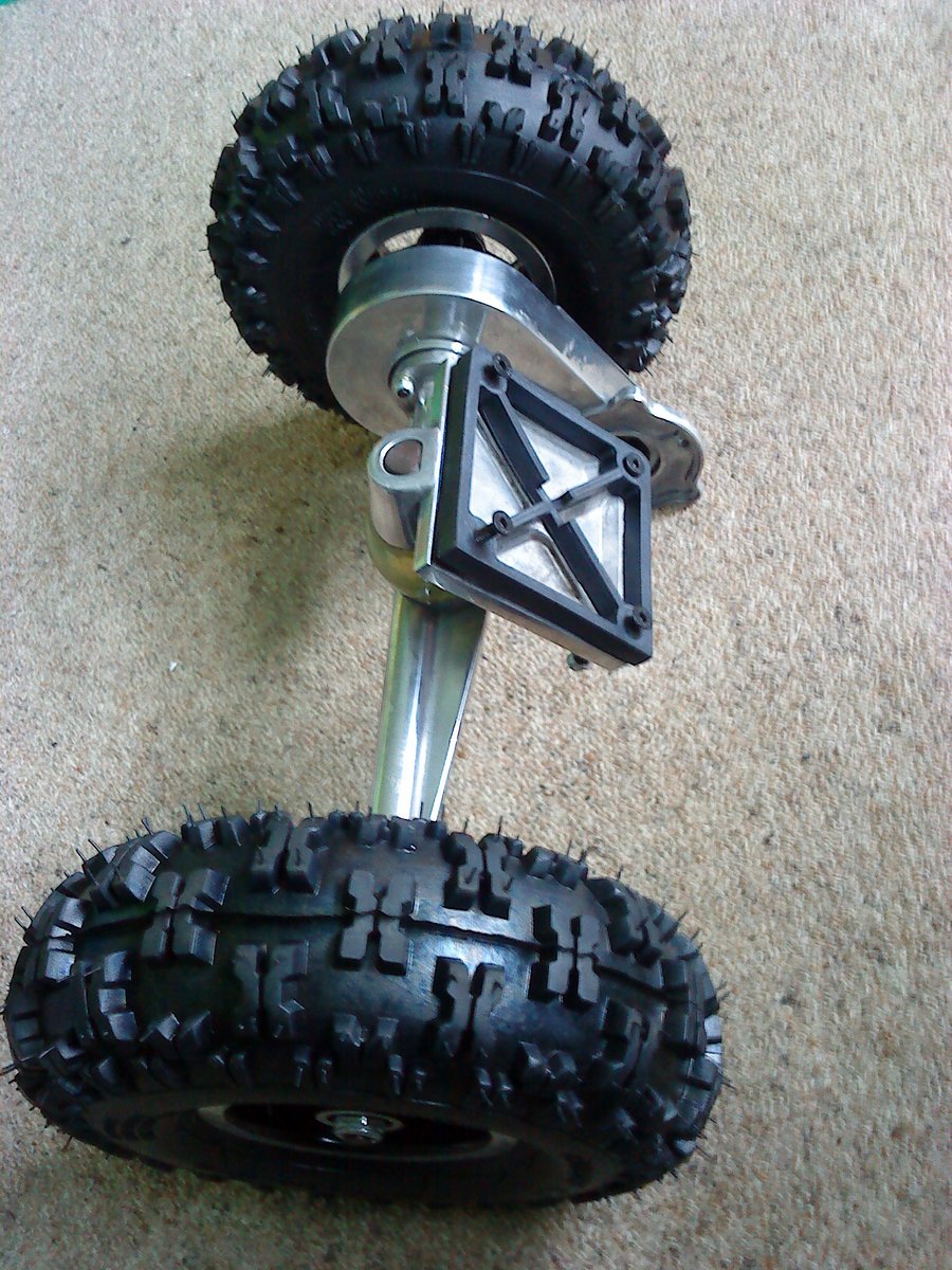
The wheels and axles where brought of TradeMe, New Zealands equivalent of eBay. I needed axles and wheels that would allow me to transfer power from the motor somehow. After much consideration, and tossing up the idea of making them myself, I decided to buy some axles and wheels that were designed for skateboards in the first place (half-cheating, I know, but it would of added so much more work to the project, and it had enough already).
There were two wheel/axle variants, a smaller package for street only use and a larger package for off-roading. I decided to go with the off-road version. They are huge! The wheels are self-sealing pneumatic tires and the axles are huge (and heavy :-(…). Although this adds a decent amount of weight to the board, they will be able to take on shallow curbs and ruts which I was worried about when flying down the streets in the dark. Being large they offer more side-to-side stability, but also increase the centre of weight, which is bad for stability. It’s a healthy compromise…
Drive Cog
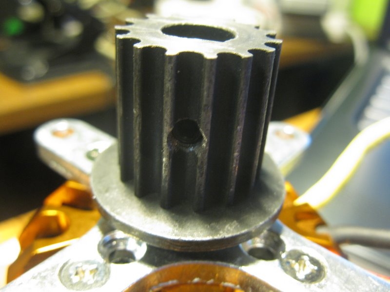
The drive cog was brought from the same place as the wheels and axles. Fortunately, the cog was designed for a 10mm shaft, exactly what my motor shaft happened to be. However, the cog was a ‘D’ type so it could deliver torque, while the motor shaft was circular. Thankfully, the kind folk at Nivens Engineering were able to machine a D into the shaft, as well as drilling and treading a hole in the side of the cog for a retaining grub screw.
Mounting The Motor To The Rear Axle
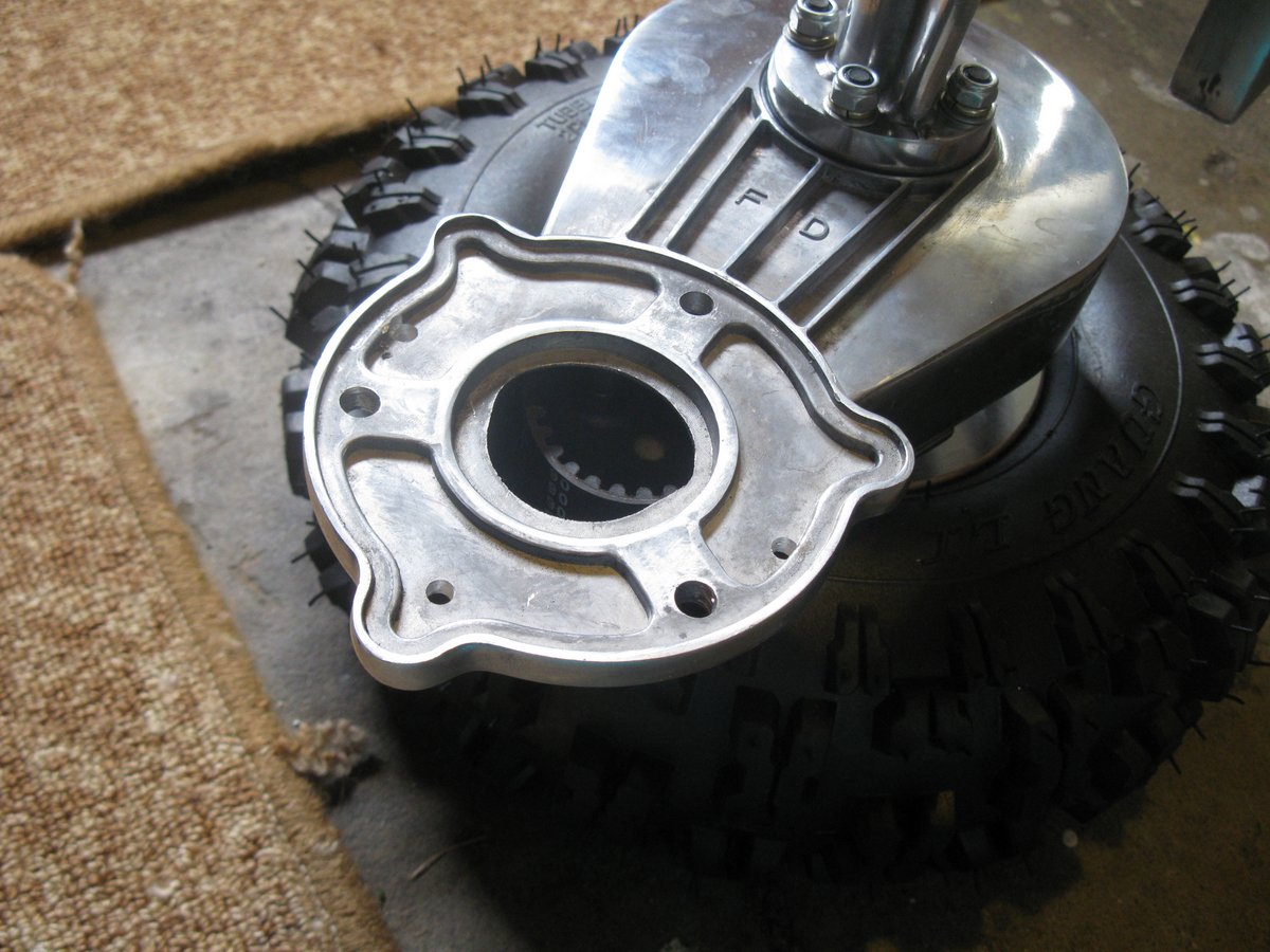
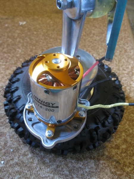
The motor mount on the rear axle was not designed for the BLDC motor (it was designed for a larger 800W brushed motor). To fix the motor in the correct position I had to drill new holes in the mount. Luckily, the BLDC motor came with it’s own mounting bracket, and even luckier was that it fitted quite nicely inside the original motor mount, needing minimal modifications. Notice the difference in size between the expected motor and the BLDC! And note that this smaller motor is 4-5 times more powerful, and lighter (ahem, as “they” quote, keep reading to find out why this figures may be wrong)!
The Prototype Motherboard
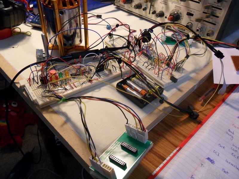
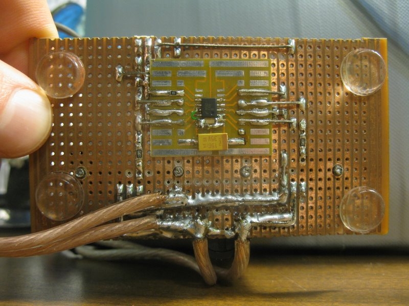
The first prototype control circuitry (aka motherboard), was assembled on strip-board. I used an ATmega8L-8PC microcontroller since the DIP package makes it easy to hand solder into strip board, requiring no breakout PCB.
Wireless Control
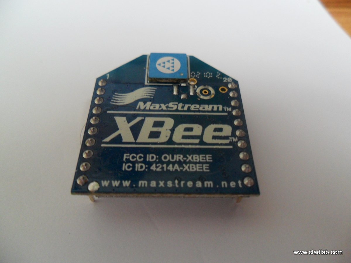
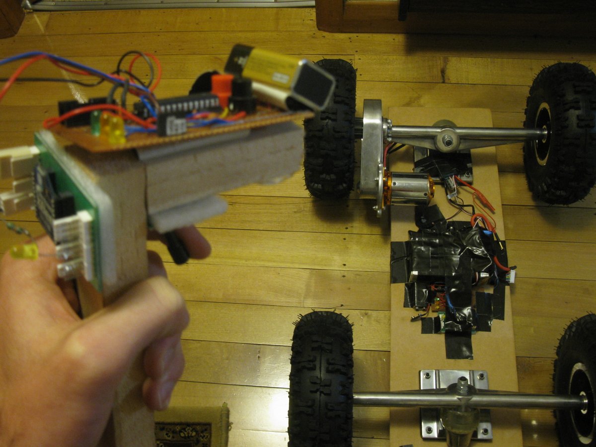
I wanted to be able to hold down a trigger in my hand to control the motor speed wirelessly. To do this I used the MaxStream XBee module, a ‘plug and play’ wireless module that accepts standard TTL serial input and output. It is used in ‘Transparent Mode’ (non API), making it very easy to use (you don’t have to worry about packetising the data or using a defined structure on the data).
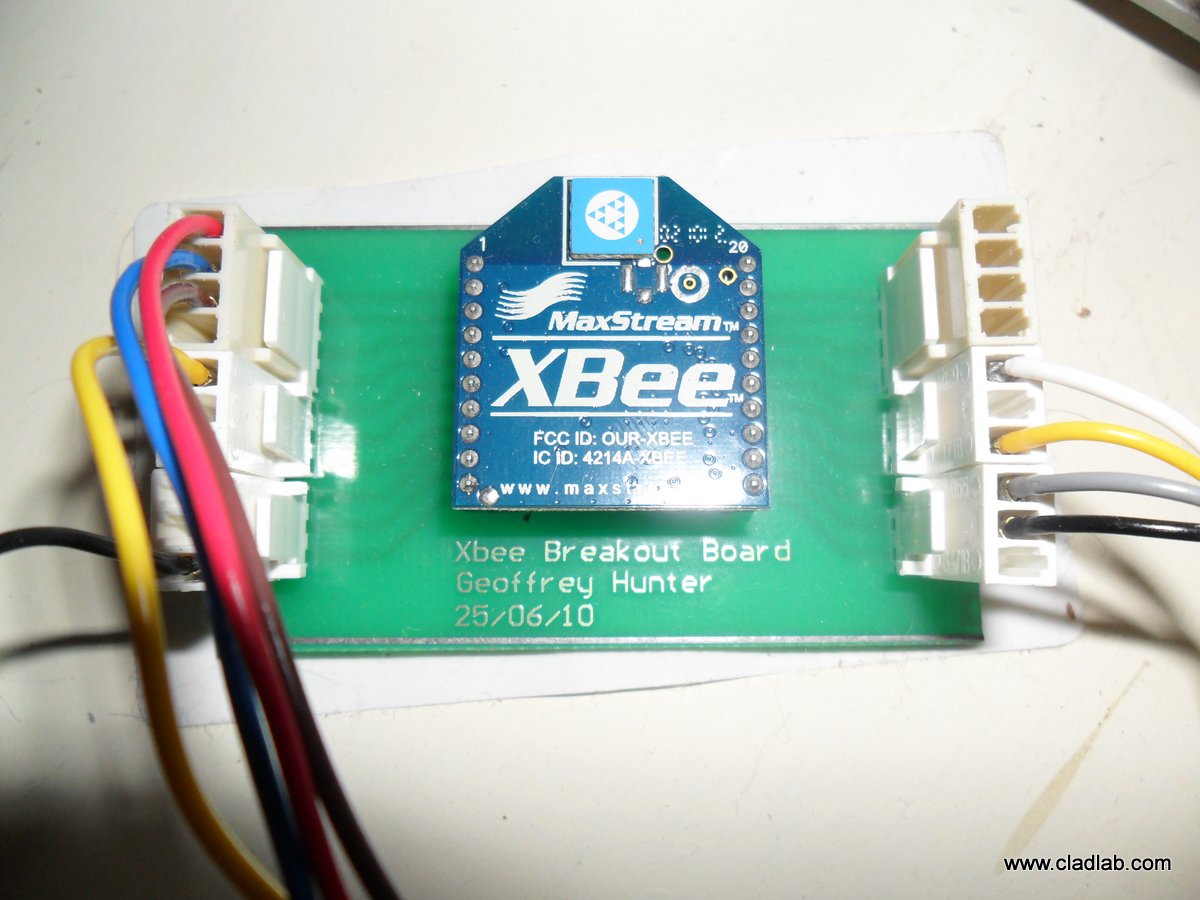
To make prototyping easier, I created a breakout board for the Xbee (the module has nasty non-prototyping-friendly 2mm pitch connectors). I managed to sneak this PCB in with a bunch of other that were being made by the University I was studying at, so these were done for free!
However, if you want your own Xbee breakout board, I suggest you look on SparkFun. They have much better looking and cheaper Xbee breakout boards, along with Dongles, so that you can customise the way the Xbee module works with the free X-CTU software.
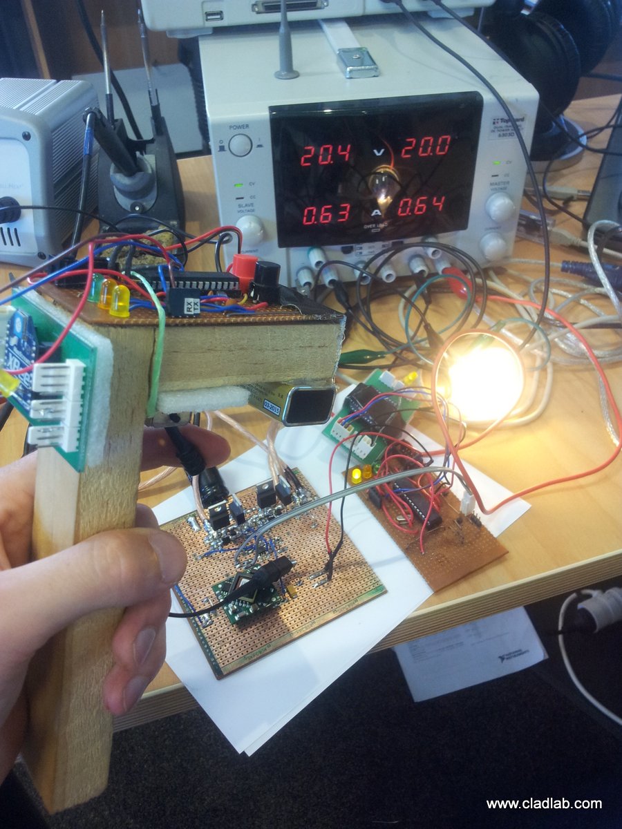
The first wireless controller looked awesome, if your a prototyping geek like me. However, any product designer would of barfed as soon as they glimpsed at it’s rat’s nest of cables and duct tape.
RPM Counter
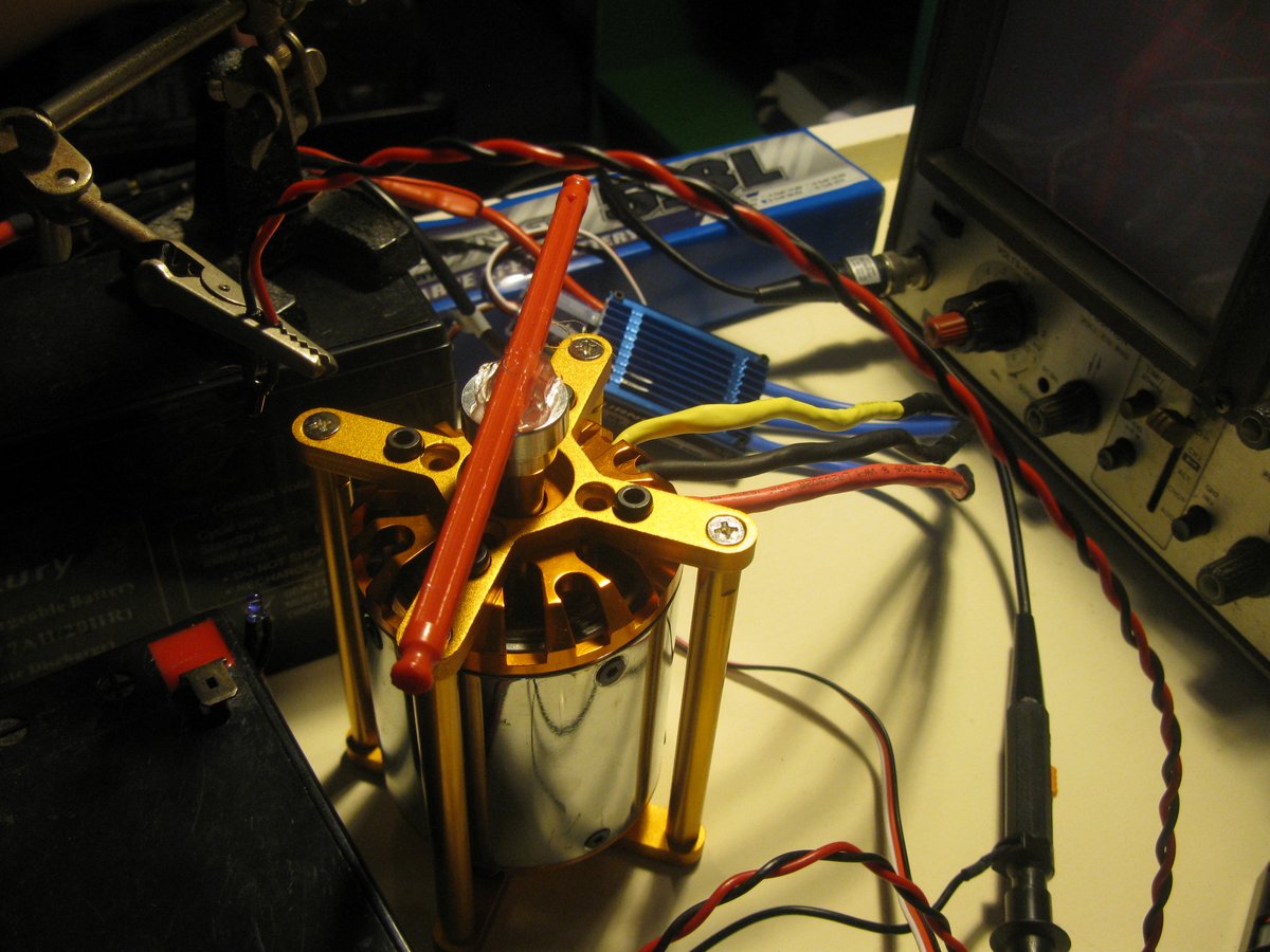
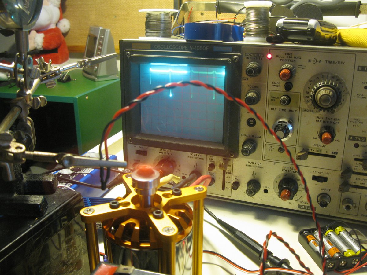
I needed to measure the RPM range of the motor to work out what gearing I needed between the motor and the wheel. To do this I glued a section of KNEX (basically a plastic rod) onto the rotor and placed an infrared emitting diode and transistor either side of the KNEX.
When the motor spun, the infrared transistor would essentially switch from ‘off’ to ‘on’ when the beam was blocked by the KNEX. This happened twice per revolution and I could measure this on my oscilloscope. The infrared diode and transistor set-up to the left of the motor. My old-school oscilloscope picking up the rod cutting the infrared beam twice per revolution.
Table showing the calculations for working out the maximum and minimum rpm of the motor.
Power Requirements
The power requirements of the circuits and motor determine the run time of both the skateboard unit and the remote control. They also determine the size and complexity of the power circuitry. Larger power requirements demands larger heatsinks, or better efficiency voltage conversion circuitry (e.g. a simple and cheap inefficient linear voltage regulator versus a more complex but efficient switch-mode power supply).
Skateboard Power Requirements
The skateboard power is largely used by the 800W (max) motor. A small amount will be taken up the LED lighting (both front/rear and skirting lights), a smaller amount by the comms, and a tiny amount by the micro-controller itself. A breakdown of the power usage is below:
The battery voltage is nominally 48V, although this can be as high as 53V and as low as 42V depending on the charge. This is dropped down to 12V by a switch-mode power supply for the lights. Two linear voltage regulators drop the voltage even further to 3.3V for the digital circuitry.
Remote Power Requirements
The remote uses far less power than the board, and is largely consumed by the comms and leds. The remote is powered from a 9V Ni-MH battery with a capacity of 180mAh (I’m hoping to get some higher capacity 300mAh battery as the run time is currently only about an hour). This is dropped down to 3.3V by a linear voltage regulator to power all of the circuity.
Electric Skateboard v1.0
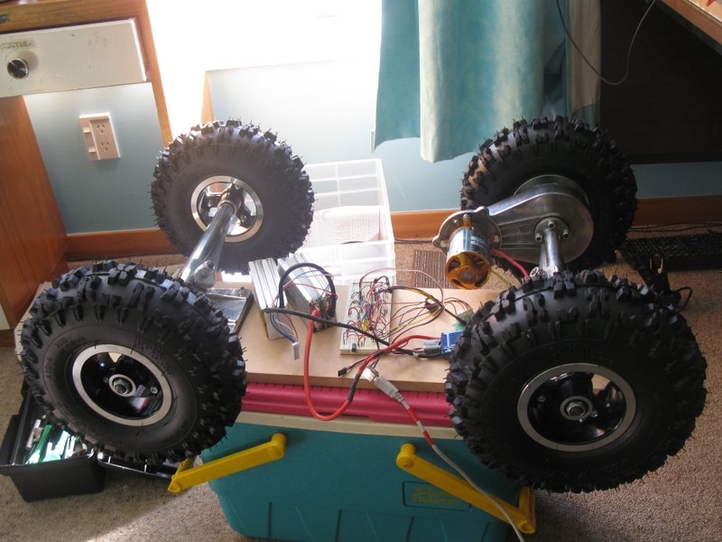
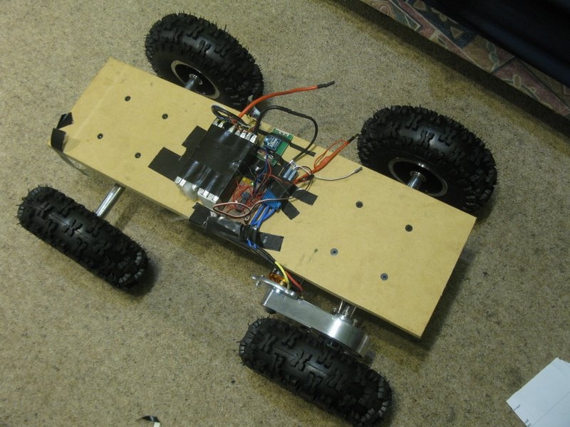
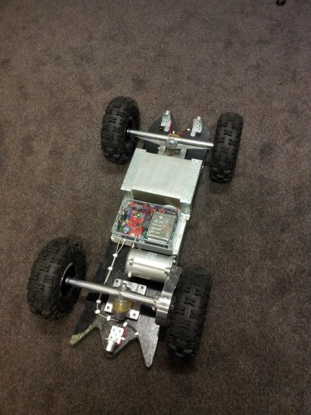
The test board was to make sure the basic principle worked, and to make sure I hadn’t done something fundamentally wrong such as brought motor that was utterly too small or wheels/gear-ratio combo that wouldn’t work properly. The mechanical part was as simple as mounting the axles onto a piece of MDF.
The proto-type electronics were stuck onto the top, and after lots of testing and debugging, I finally managed to get it moving! With code bugs and problems using the RC trigger pot, I wasn’t able to get the electric skateboard up to full speed, but I still managed to break the 30km/h mark. The ESC got damn hot! This may need heatsinking in the future…
After fixing up the code, it was time to take the board a little further down the road. I decided to heatsink the ESC to the trucks after discovering it was burning hot after the last test. I covered the heatsink side of the ESC with heat transfer compound and duct taped it securely to the rear truck.
I also thought it would be nice to ‘mount’ all the electronics on the underside of the board.
Getting ready for a test run to work!
An Explosion
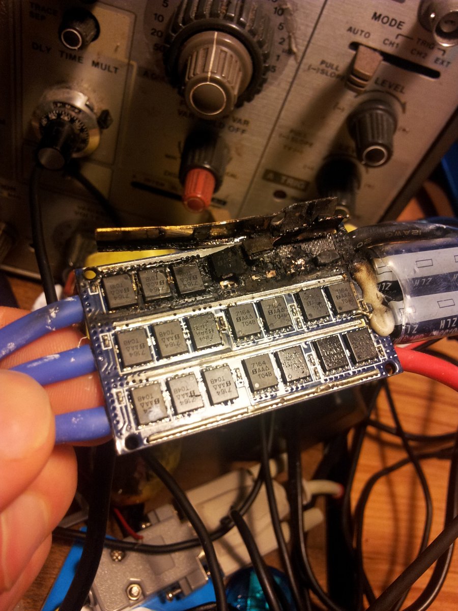
Unfortunately, the BLDC ESC blew up about half way to work (a few kilometers into the test run). My best guess is that both the RC plane designed motor and controller were under-powered for the job (even though rated well enough). The picture on the right shows the blown ESC.
The New Motor + Battery
However, after I made the change from a BLDC to brushed-DC motor, I made an upgrade to a 48V, 10Ah LiFePO battery! However, the first battery they sent was the wrong size (I had ordered a flatter shape, could you see this fitting on the bottom of a skateboard?).
And along with this battery, I got a brushed DC motor.
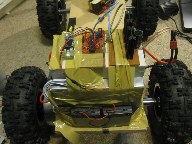
The electronics mounted onto the top of the second prototype.
Custom Half-Bridge
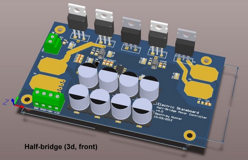
The next attempt at motor control was done, using a brushed DC motor and a homemade half-bridge controller.
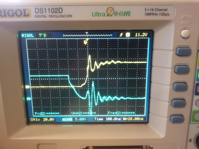
Alas, it kept blowing up (see the post Skateboard H-Bridge Blew Up (for the +10th time). The MOSFETs were getting very warm, and there was an oscillating signal on the gates of the half-bridge MOSFETs.
I was also getting oscillations on the half-bridge bus voltage (+48VDC). The bulk capacitor was getting very warm.
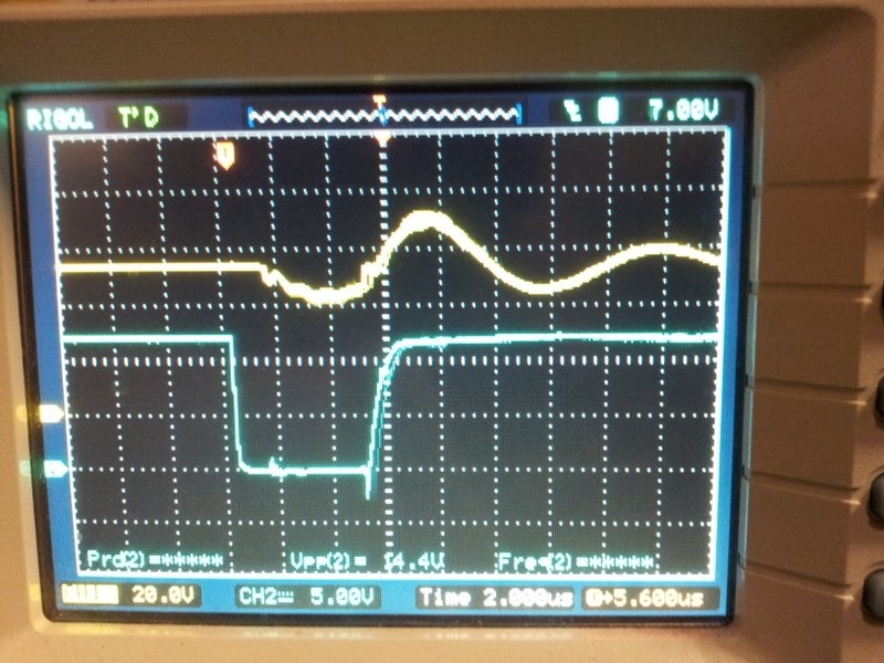
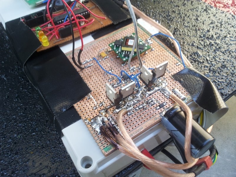
It turns out I did not have enough bulk capacitance, causing the voltage to oscillate due to the MOSFET switching. This was causing high currents through the bulk capacitor and heating it up due to its parasitic resistance (equivalent series resistance, or ESR). I only had 200uF, which is pretty insignificant. The following image show the initial bulk capacitor hanging of the side (it wasn’t enough).
Alarm Prototype
I wanted a motion alarm on the skateboard so I could “arm” it when locking it to a bike rack in public places.
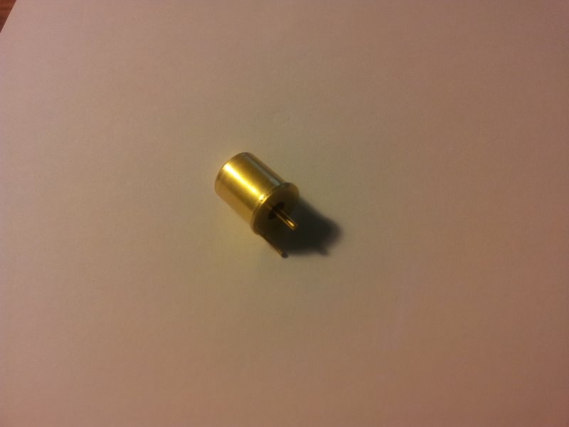
I used the MS24 motion sensor.
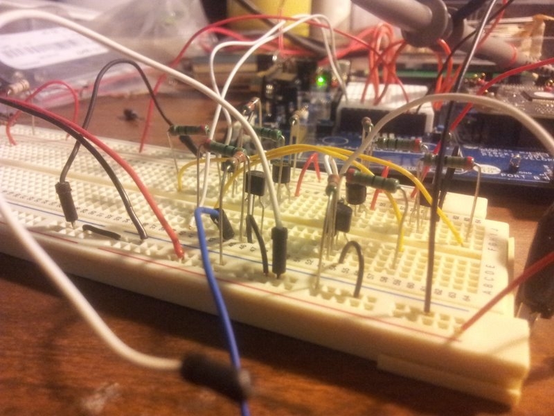
And built this test circuit on breadboard. There is a PSoC development kit in the background.
The Final PCB Design
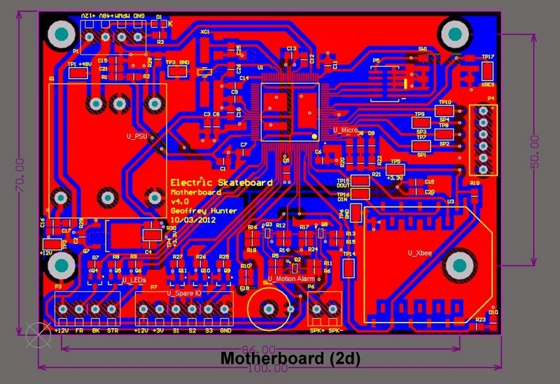
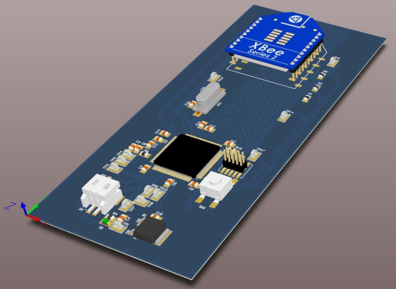
Once the electronic design had been verified with the prototypes, it was time to get some professional PCBs made. The PCBs were designed in Altium. I used a PSoC 5 microcontroller from Cypress for the final designs.
The Schematics
Motherboard PCB
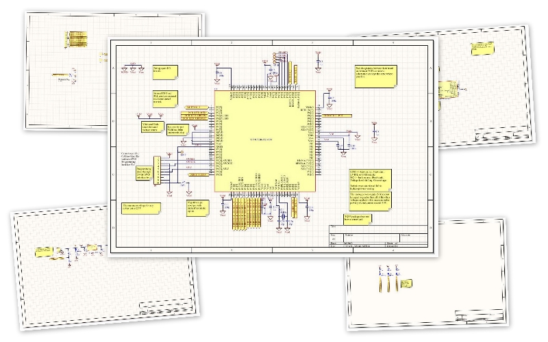
The schematics for the motherboard can be downloaded here.
Remote Control PCB
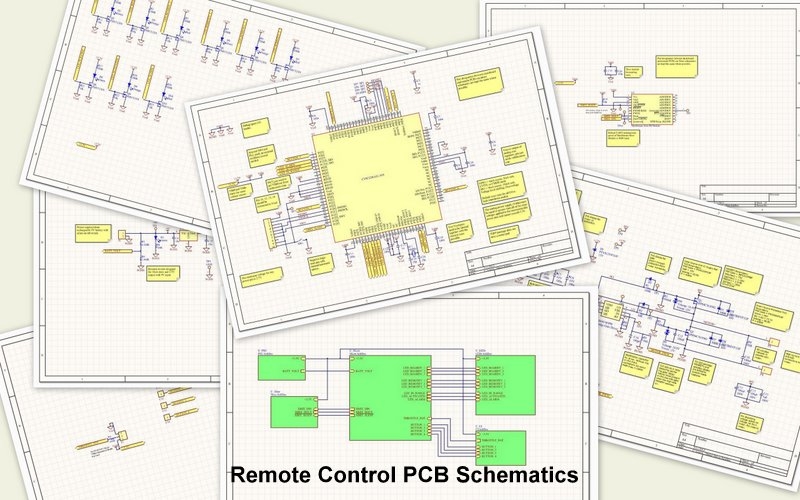
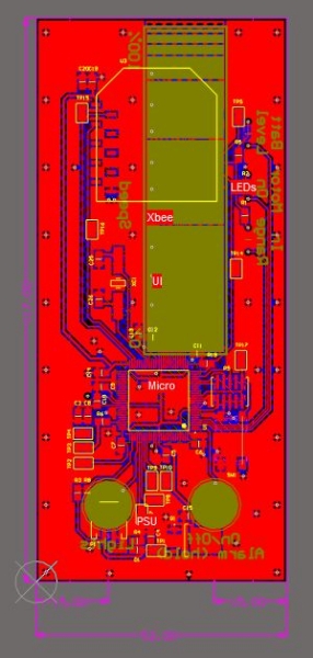
The schematics for the remote control can be downloaded here.
Motor Driver PCB
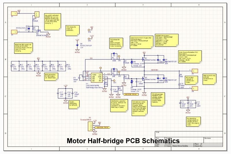
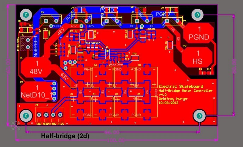
The schematics for the Half Bridge Driver v1.1 (please remember, this is the one that kept blowing up) are shown below. From v1.0->v1.1, I removed the low-side MOSFET switch that was designed to disconnect the battery. This didn’t work when tested, so I replaced it with a high-current relay instead (still operating from the same key-switch). I’m still at a loss to as why this did not work. I made multiple prototypes, and enlisted help/advice from many engineering friends and even a 40-year old motor control and design veteran, yet still coaxed the magic smoke out of ever PCB I tested.
They can be downloaded here.
PCB Manufacturing
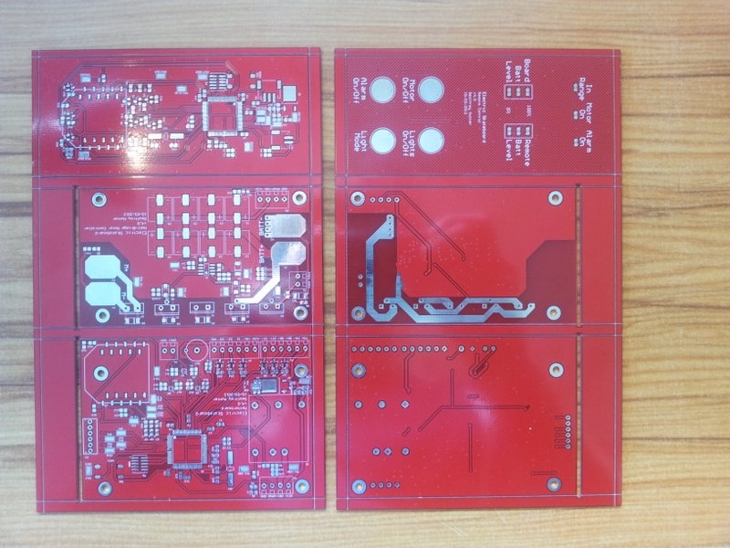
Once the PCBs were designed, I had them etched by PCB Cart (see the Electrical Suppliers page). The PCBs came back in a colour what I like to call ‘spew orange’, which was less than ideal, since I wanted orange.
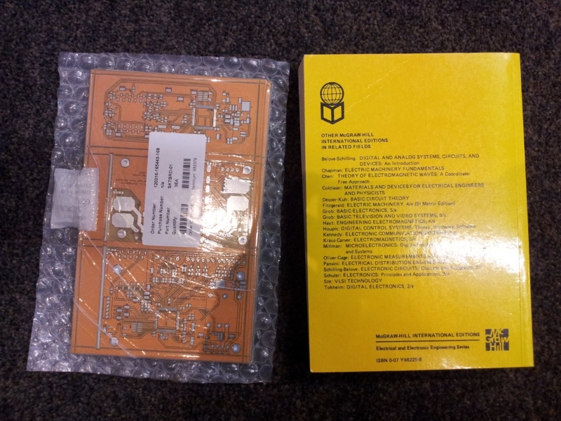
I got to the point where PCB Cart would redo them in red if I paid for half the manufacturing cost. They came back with a much better colour scheme (and you can actually read the silkscreen).
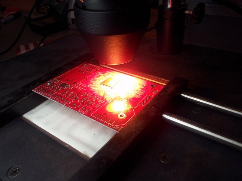
See the post Electric Skateboard PCBs Arrived In The Wrong Colour for more info. Most of the components were populated by hand, with the help of a infrared rework station for soldering the PSoC 5 chips (in TQFP packages).
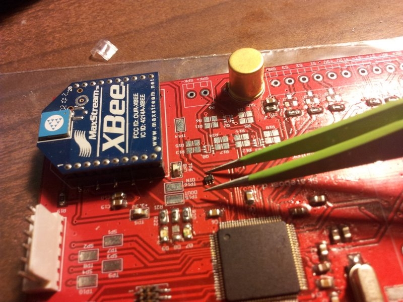
The hardest things to solder were the transistors for the speaker h-bridge. They were in the tiny 6-pin packages shown below.
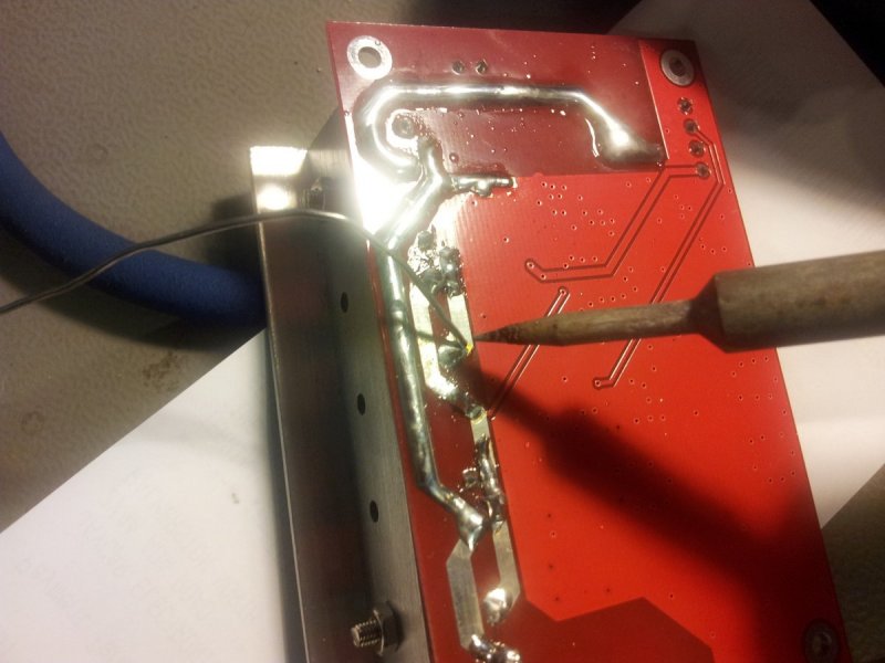
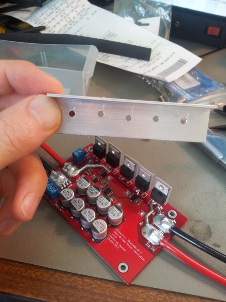
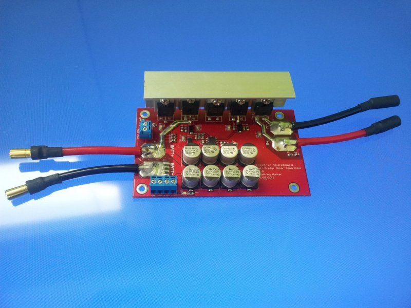
I designed the half-bridge motor controller high-current tracks to have no soldermask. This enabled me to thicken up the tracks with solder.
I also put all of the MOSFETs on the half-bridge in a row, so that I could easily attach a heatsink to them. The heatsink was made from a piece of Aluminium “T-section”.
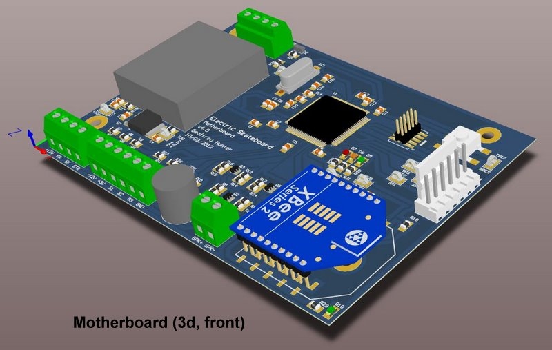
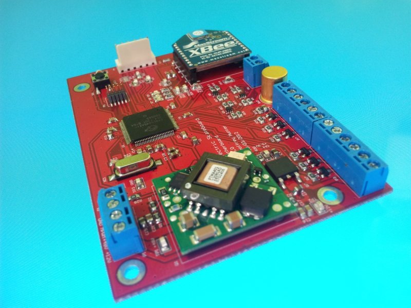
The finished motherboard.
The finished half-bridge motor controller (which didn’t work).
Writing/Testing Firmware
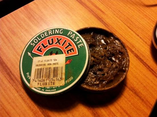
I ran into plenty of mysterious problems while testing the firmware, such as LEDs randomly turning on and off, microcontrollers programming and then refusing to be recognised, and more. I eventually discovered the problem was the flux I had used, Fluxite, which it actually a plumbers flux and not designed for electronic circuits. The flux residue (present even when the PCBs were ultrasonically cleaned), absorbed water and became conductive, causing micro shorts all throughout the circuits.
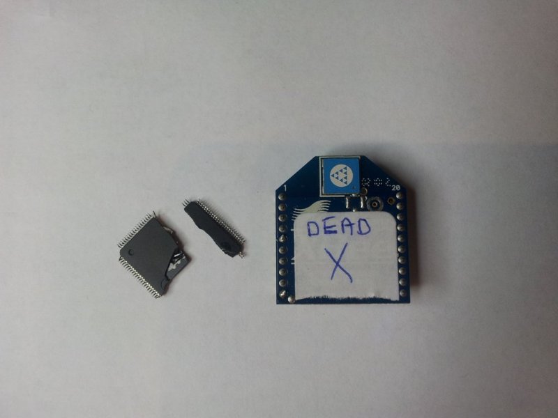
I managed to blow up and Xbee and PSoC microcontroller while testing. I accidentally connected two circuits with grounds at a potential difference of over 30V.
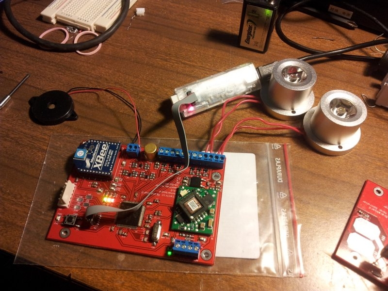
I was very happy once the PCBs finally powered up and were working correctly.
Fibreglassing
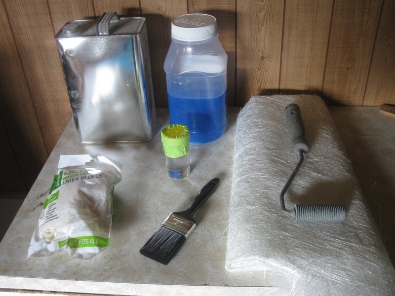
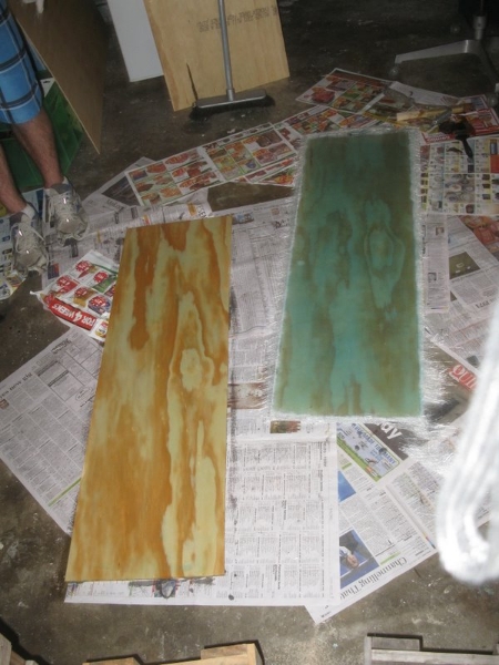
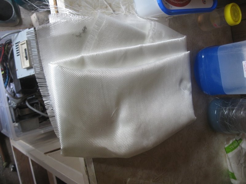
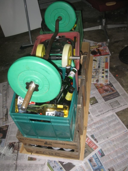
The final board was made from fibreglass and plywood. Here is an image of all the gear I used.
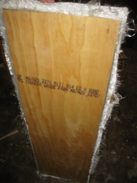
The skateboard ‘board’ is hand-made from fibreglass and plywood. The structural part is made from two layers of 4mm thick, 3ply wood with 3 layers of Fibreglass chop stran mat in the middle, held together with polyester resin.
The two pieces of plywood and wet (at the time) fibreglass were pressed together by adding weights onto the top of the board while it was on a flat surface. The board was not curved as some (well, most) longboards are since it would have taken way too much time (this project took enough time already!), and would have made it hard to mount the battery and electronics to the underside of the board. The resin was mixed with 1% catalyst (10mL catalyst for every litre of resin) to provide long enough time to work with the board (it was the middle of summer, so the resin would set quickly). It is not advisable to fibreglass so many layers at once, but I managed to get away with it. The plywood was roughened with 40grit sandpaper to improve adhesion with the fibreglass.
When making the board for the first time, I accidentally added 1mL of catalyst per litre instead of 10mL (it’s meant to be 1%, oops!). This meant the resin didn’t set, and I was lest with a stick mess of wood, fibreglass and goop. I had to throw out the entire board and start over again. It was about a NZ$60 mistake
There is a layer of thin fibreglass ‘Airplane’ cloth on the top and bottom sides of the plywood to provide a fibreglass surface for the gell-coat paint (gell-coat paint does not stick well to wood). This cloth is so thin that it does not add any mechanical strength to the board, or much weight. It used about 100mL or resin per side.
After all the fibreglass resin had set, I was left with a rectangular board that I could then cut into the correct shape. The board ended up being 12mm thick, 4.5mmx2 from each of the pieces of plywood (they are meant to be 4mm, maybe they swelled a bit when the resin was added?), and 3mm from the 3 layers of fibreglass chopstran mat in the middle. The rigidity of the board was a complete guess (I had made a skateboard from fibreglass and plywood before, but it was a different size and many years ago), so it was not a surprise that the board was a little too flexible for my liking. The greater the flexibility, the nicer it is to ride (more responsiveness and shock-absorbing capability), but the greater risk of it snapping and the harder to mount items onto the underside of it.
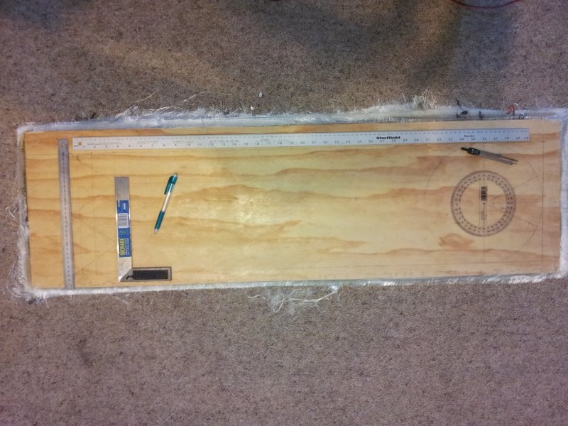
The board shape was designed in Alibre.
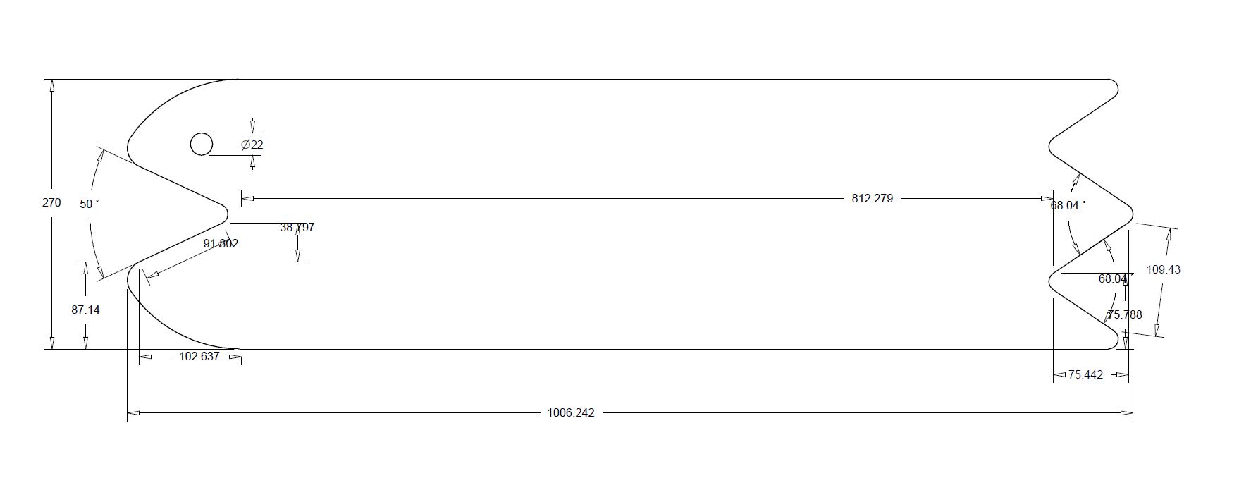
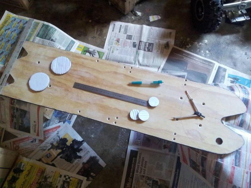
Drawing the lines to follow with the Jigsaw using rulers, protractors and compasses.
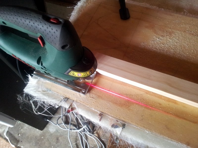
Cutting the board outline out with a jigsaw.
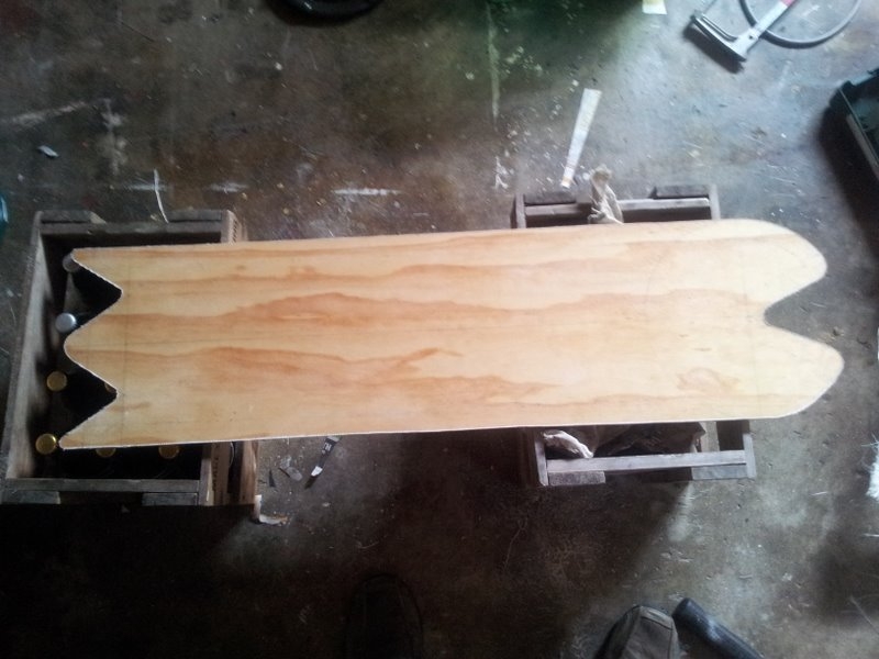
The end result!
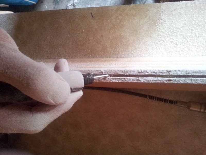
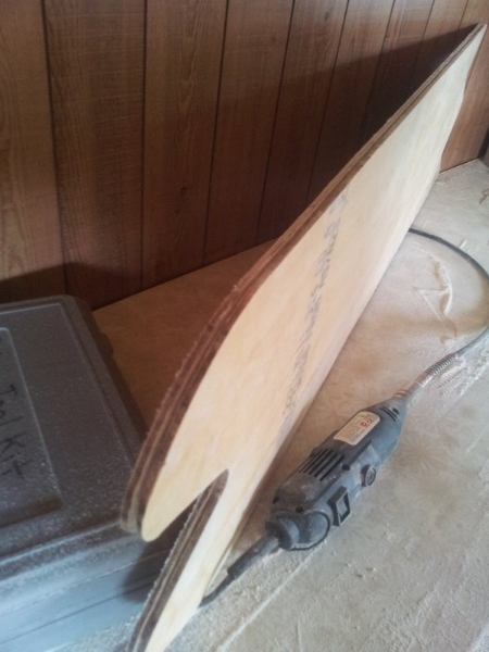
The idea was to create an outline of the board which glowed at night, using E-wire. The electrical E-wire needed a groove to sit in that ran around the perimeter of the board. I made this groove with a dremel and a spherical routing attachment.
Painting
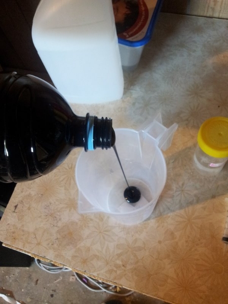
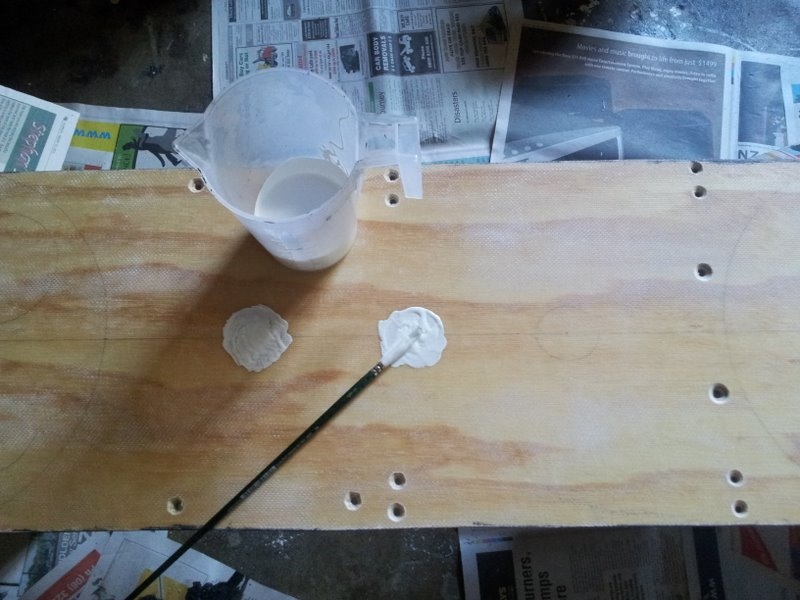
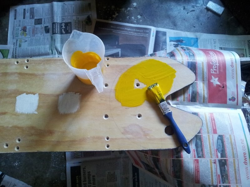
Once the fibreglass board was cut to shape, it was time to paint it! I used “fibreglass-like” paints that use fibreglass resin and a solid powder pigment to provide the colour.
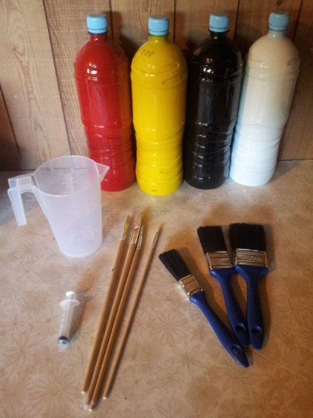
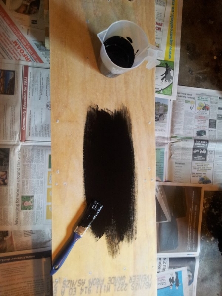
Black on the bottom side was the first colour to go on.
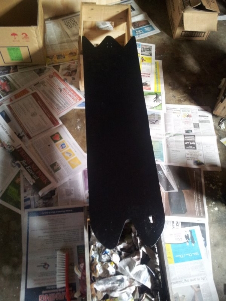
The finished underside (the easy part).
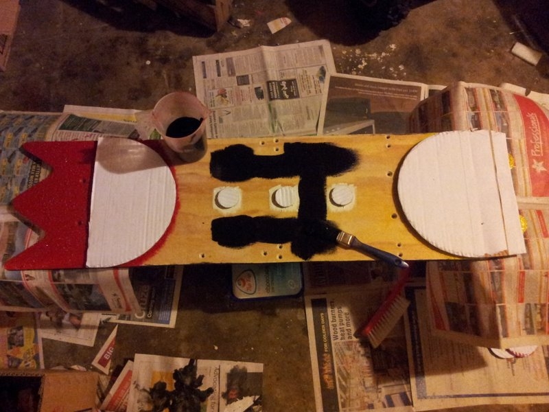
The top-side had all the pacman artwork, so I had to make masks to protect certain parts.
Then I started painting all the coloured sections.
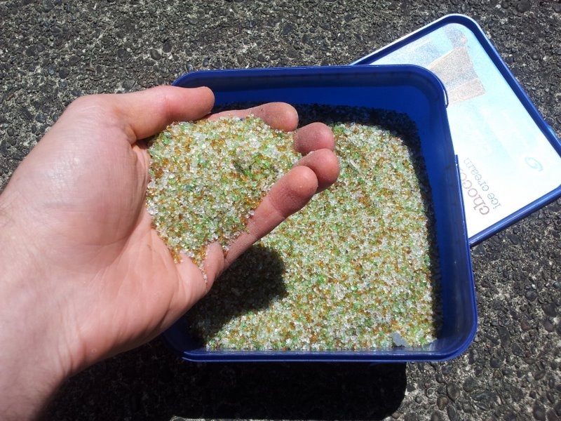
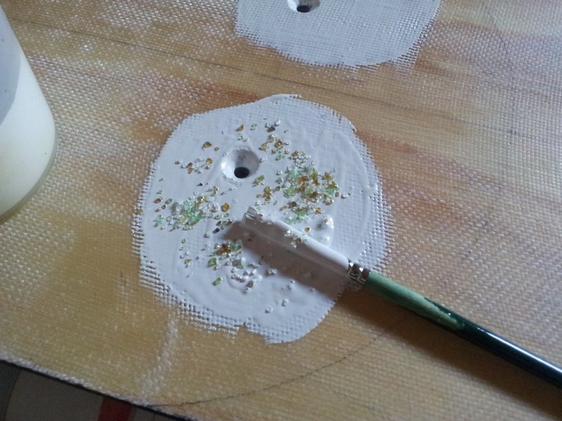
To add grip, I added crushed glass to the final layers of all the paintwork on the top surface.
Masking off and painting more areas.
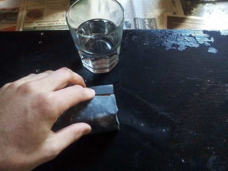
The bottom-side was sanded with wet-and-dry to give a smooth finish (the top side has a rough surface from the crushed glass, so sandpapering that would of been futile).
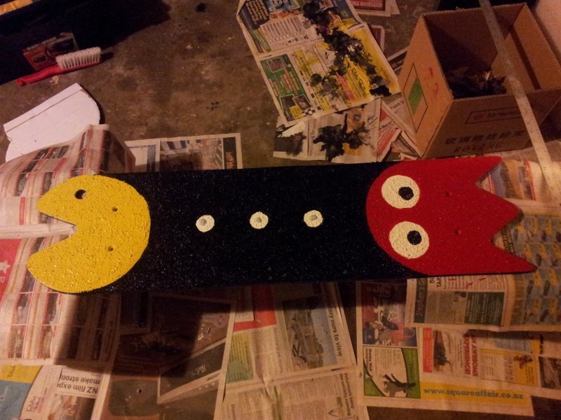
The finished paint job!
Final Mechanical Construction/Assembly
Here is me working out how to mount it onto the bottom of the board (click the pic for more info).
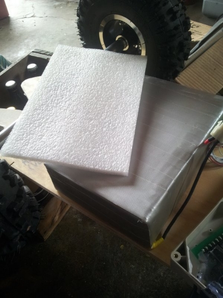
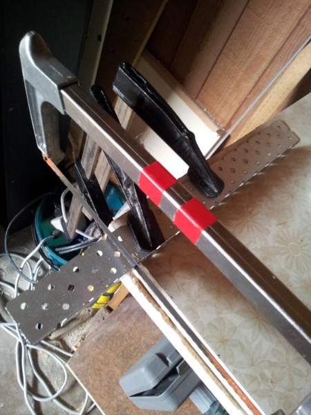
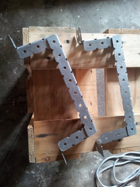
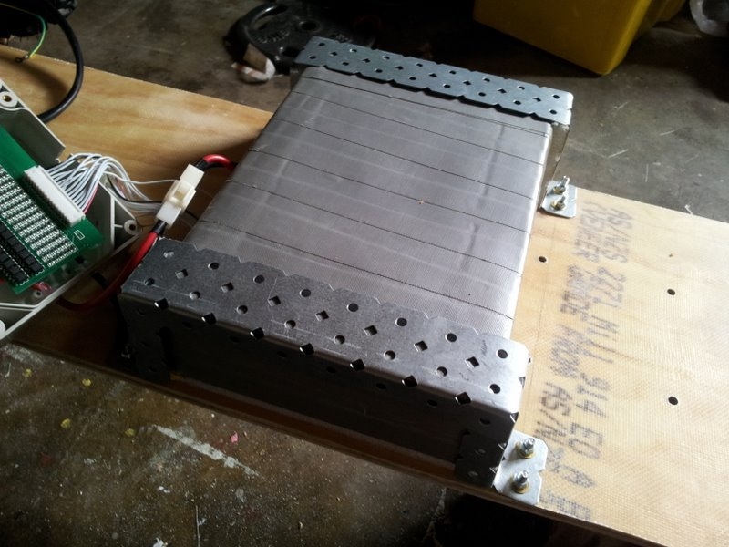
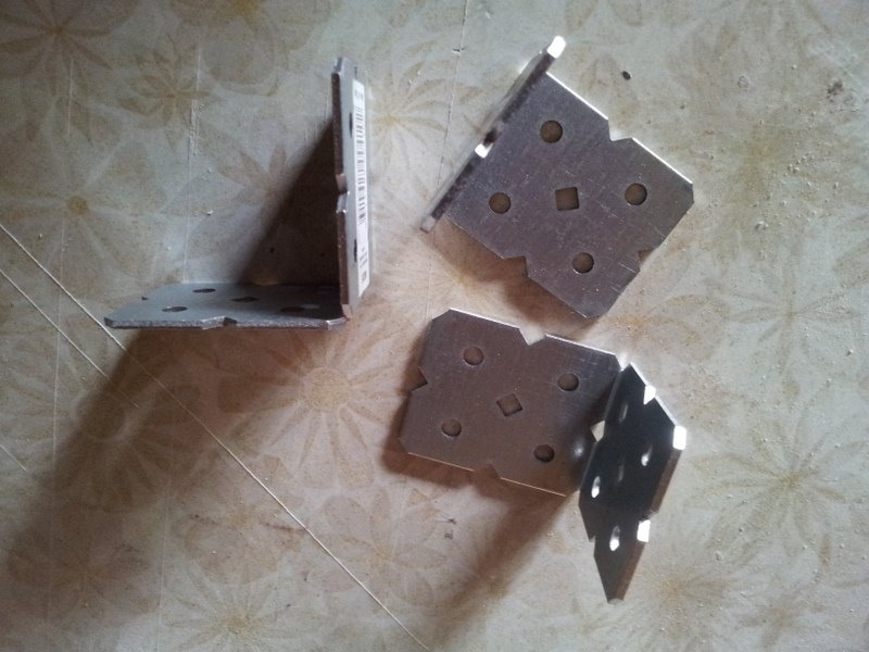
The battery mounts where made up from sections of angled steel.
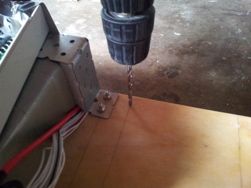
Mounting the battery onto the PCB
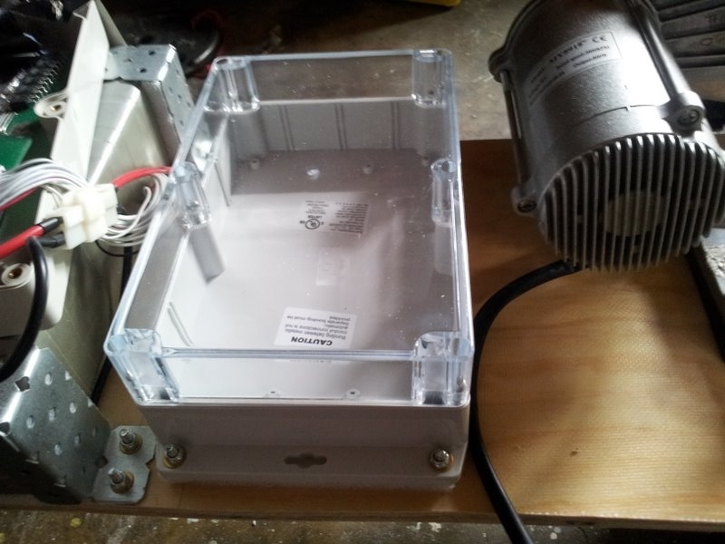
The electrical enclosure was mounted next to the battery.
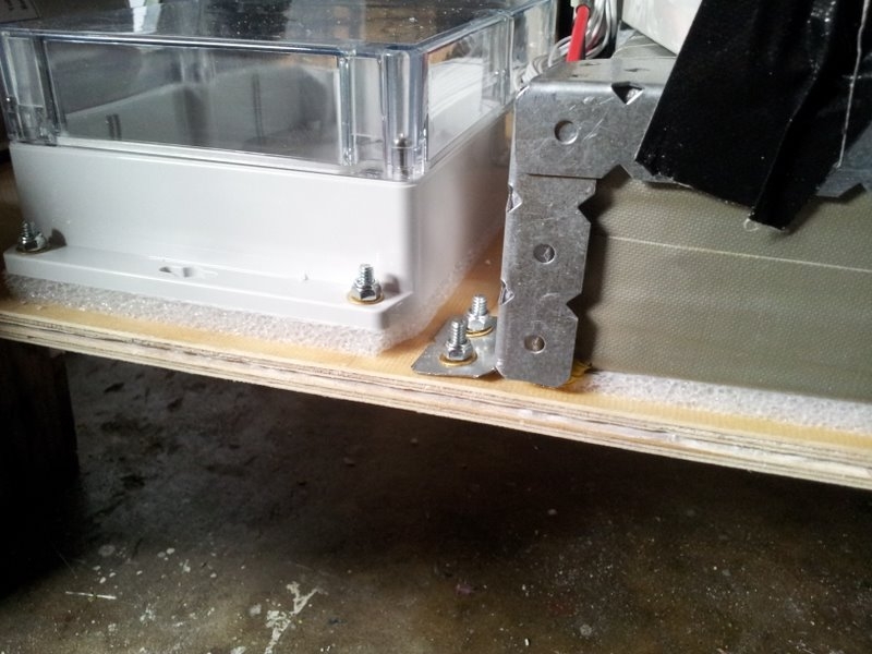
One thing to take into consideration when mounting things onto the bottom of the board is the flex of the fibreglass board, especially when someone is standing on it. This flex could cause any large inflexible object (e.g. the battery and electronics enclosure) mounted onto the underside to snap or be ripped from its mounts. The way around this was to place a piece of foam pad underneath both the battery and enclosure as shown in the image below. This allowed board flex without putting stress on the parts.
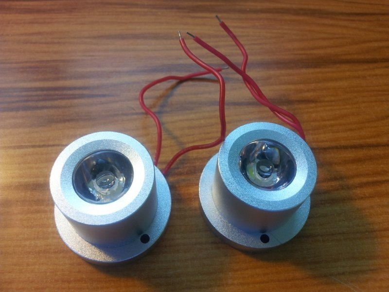
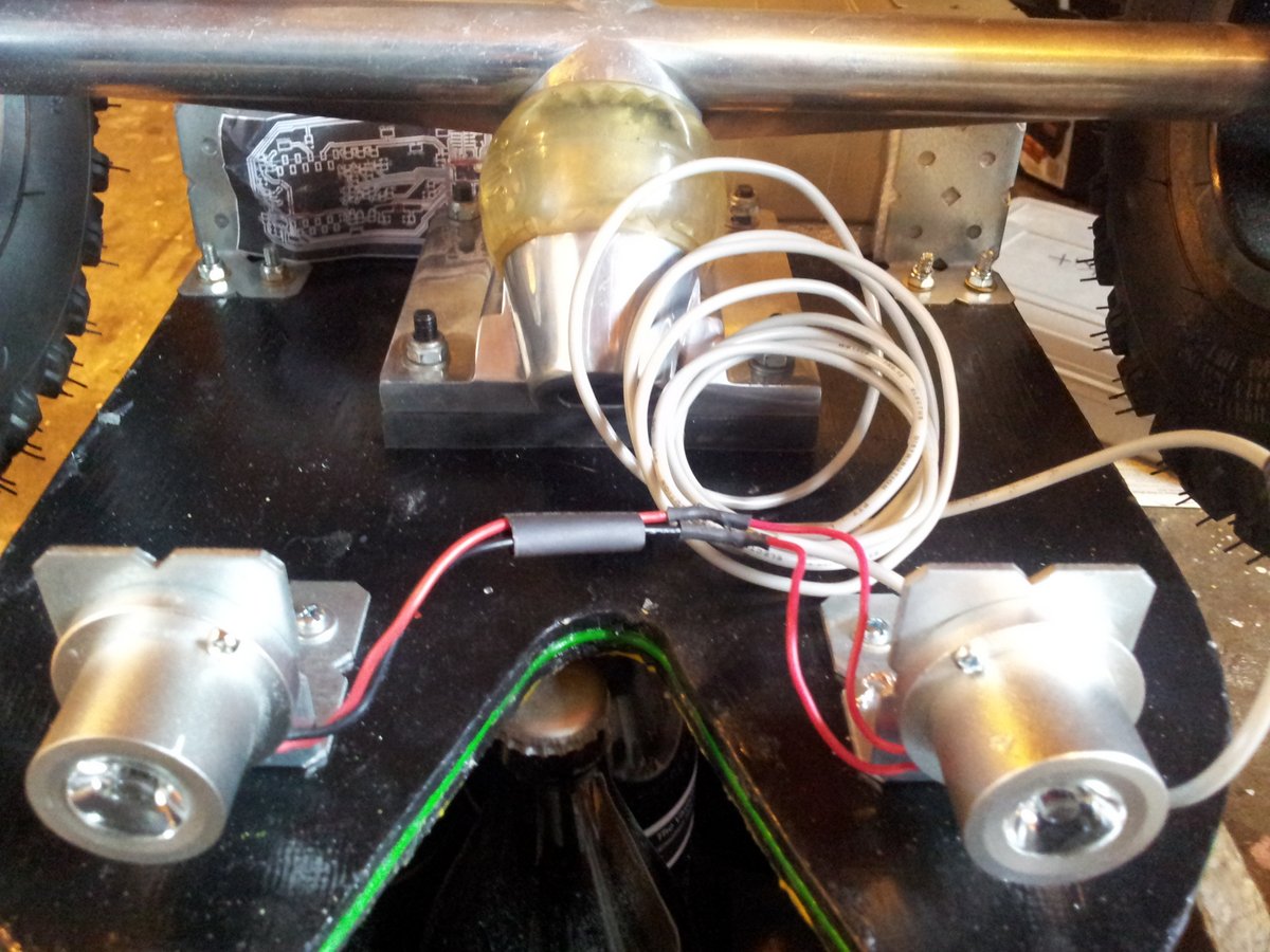
I decided to add lights to the board so that I could use it at night, and also for safety when riding on the road (this proved to be very useful)
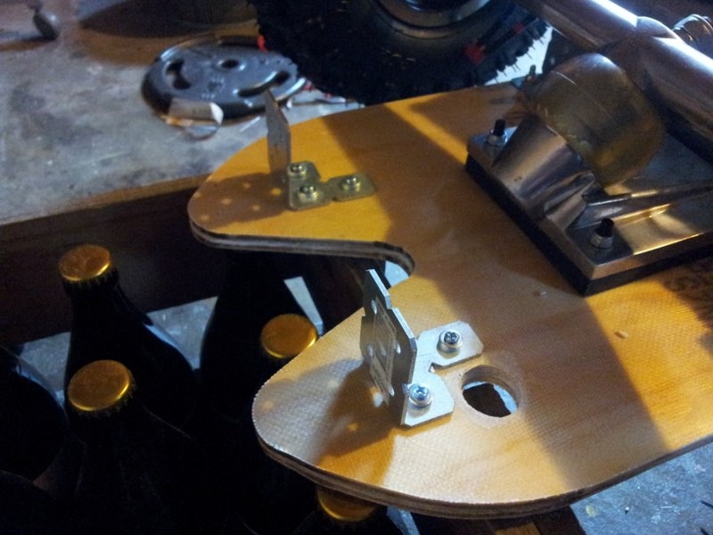
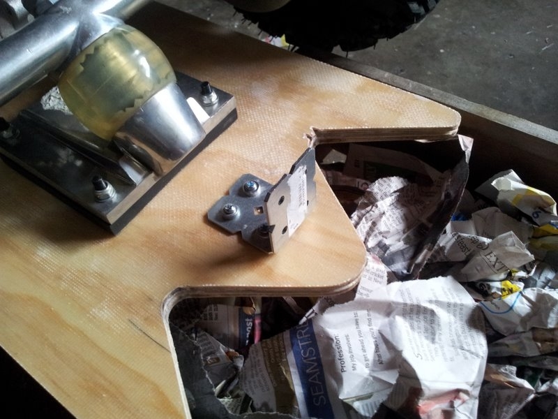
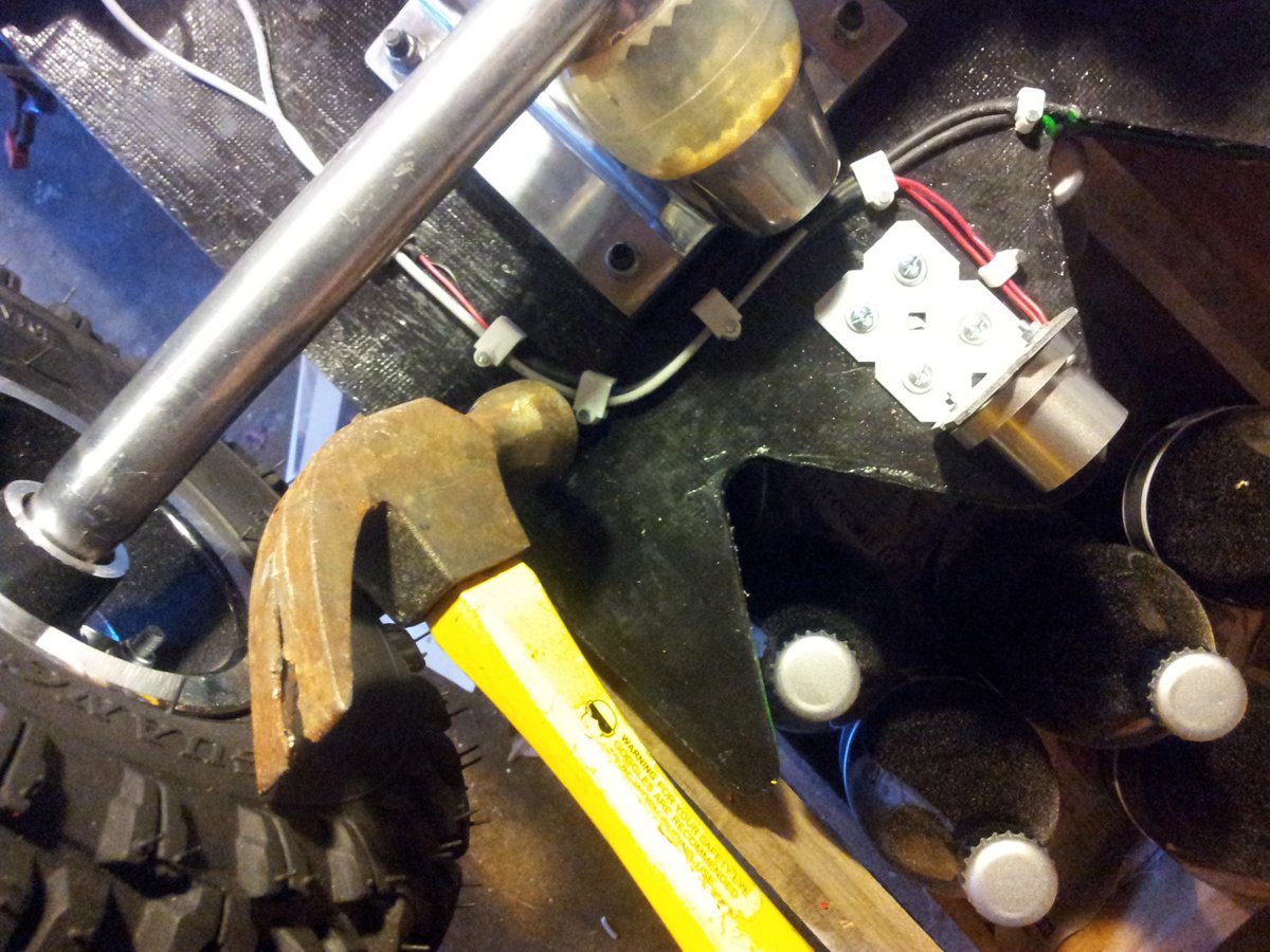
The LED lights were mounted to the underside of the PCB with some angled steel brackets.
The lights were attached with “nylock” bolts so they wouldn’t fall off.
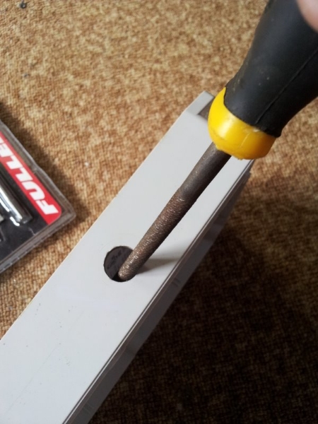
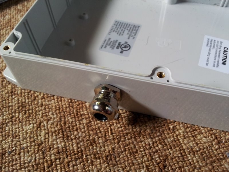
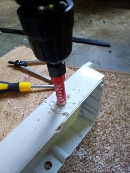
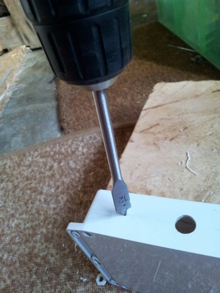
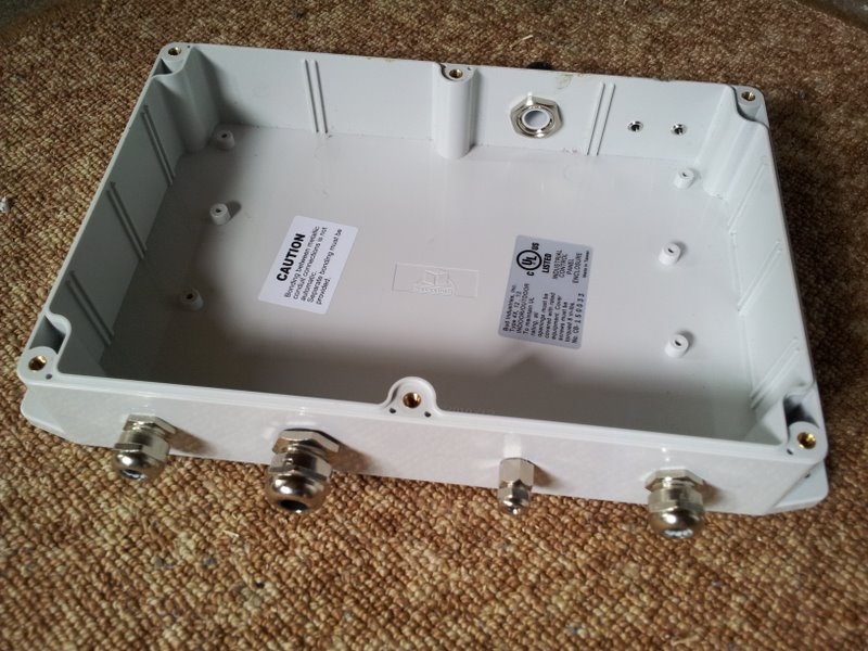
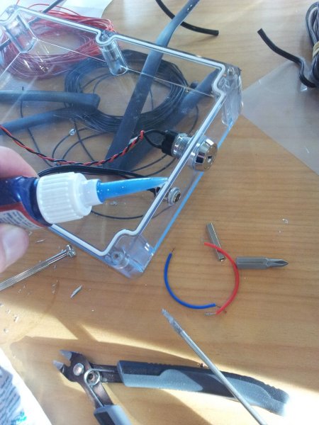
The electrical enclosure needed waterproof ways of getting cables in and out (for the battery, motor, and LED lights). I decided to use metal cable clamps. The following images show the construction.
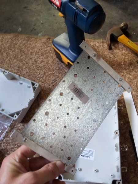
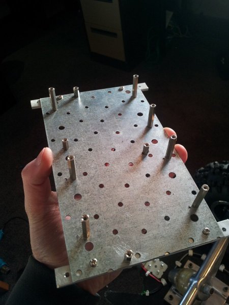
4 PCBs needed to be fitted into a pretty small enclosure. A mounting plate was made up to accommodate the multi-level PCB stack.
The stand-off supports attached to the base plate. These support the 4 circuits boards that are held above it in the enclosure.
The EL-wire driver with added standoff.
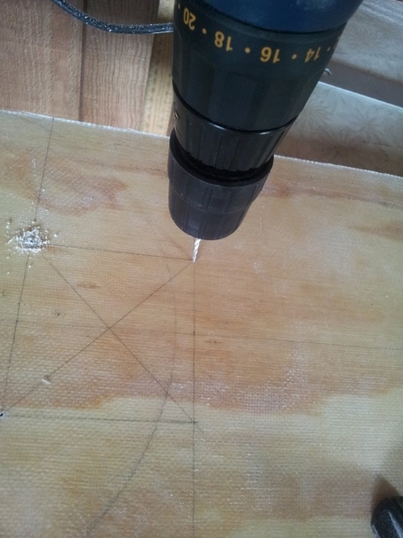
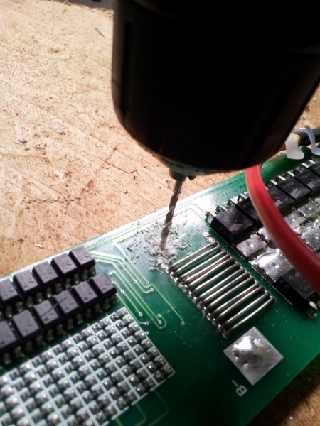
Drilling holes in the BMS PCB for standoffs.
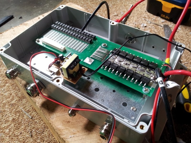
The BMS and EL-wire PCBs in enclosure.
Adding the charging port and key switch to the side of the board enclosure lid.
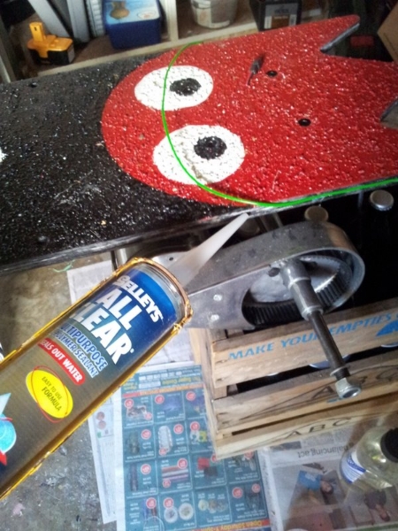
The EL-wire could now be pushed into the slot on the perimeter of the board and glued into place with see-through RV silicone glue.
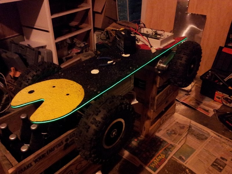
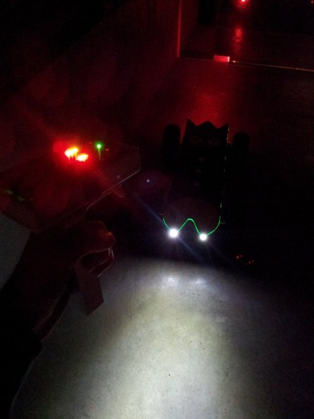
Testing the glow from the EL-wire at night!
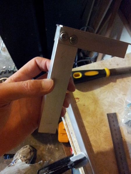
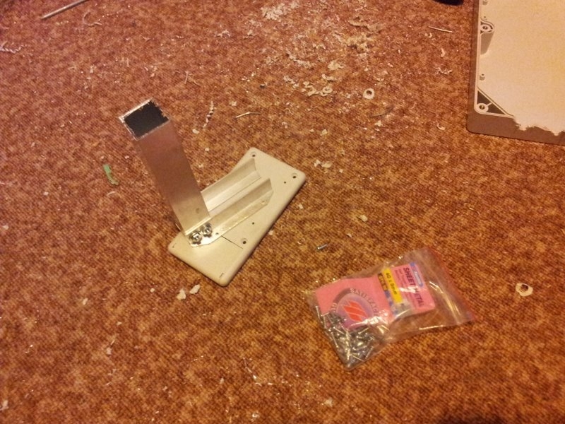
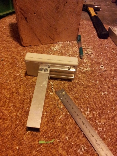
The handheld enclosure needed to be made. This was made from a Hammond electrical enclosure and various shaped sections of Aluminium tube/beam/pipe. The following image showss the making of the handle part of the hand-held enclosure.
Attaching the enclosure onto the hand grip.
The finished enclosure, apart from the trigger.
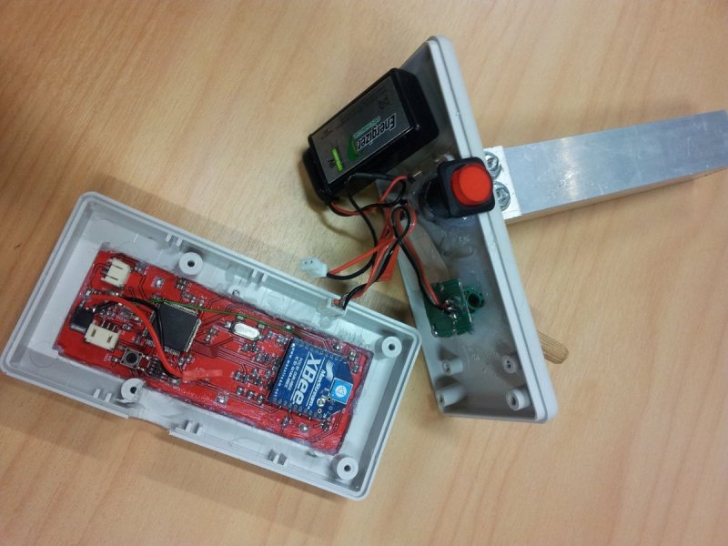
The electronics was then added to the handheld controller along with the trigger.
Giving Up On The DIY Half-Bridge
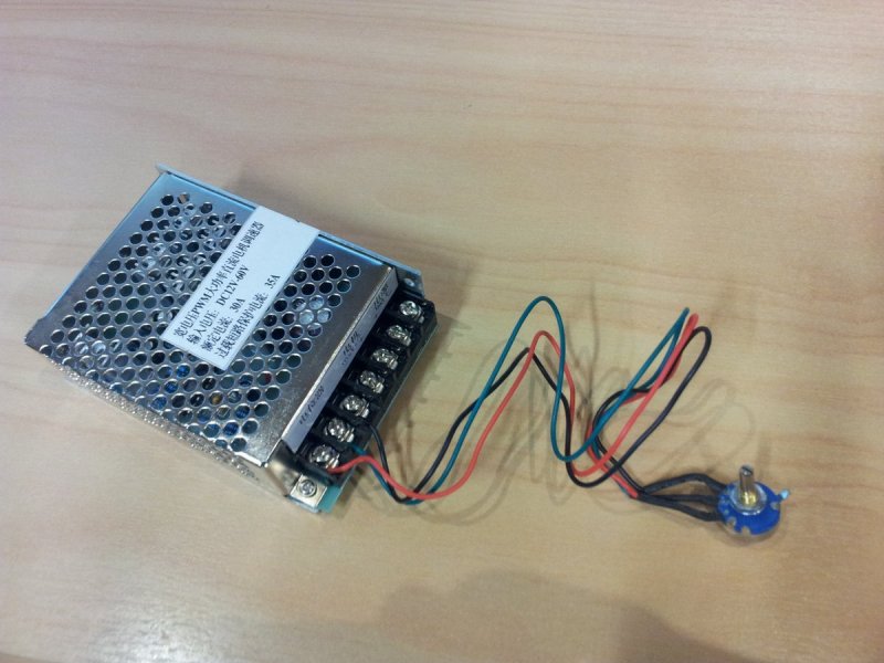
So the motor controller that I eventually ended up using…a quarter-bridge motor controller from AliExpress. Yes, a bit of a cop-out considering this board was meant to be homemade, but at least it works! The unfortunate thing about the quarter bridge is that it has no breaking ability, meaning the skateboard has not breaks. Something to fix in the future…
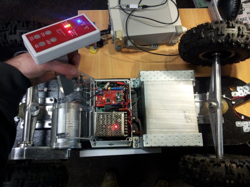
Installing the new motor controller into the enclosure.
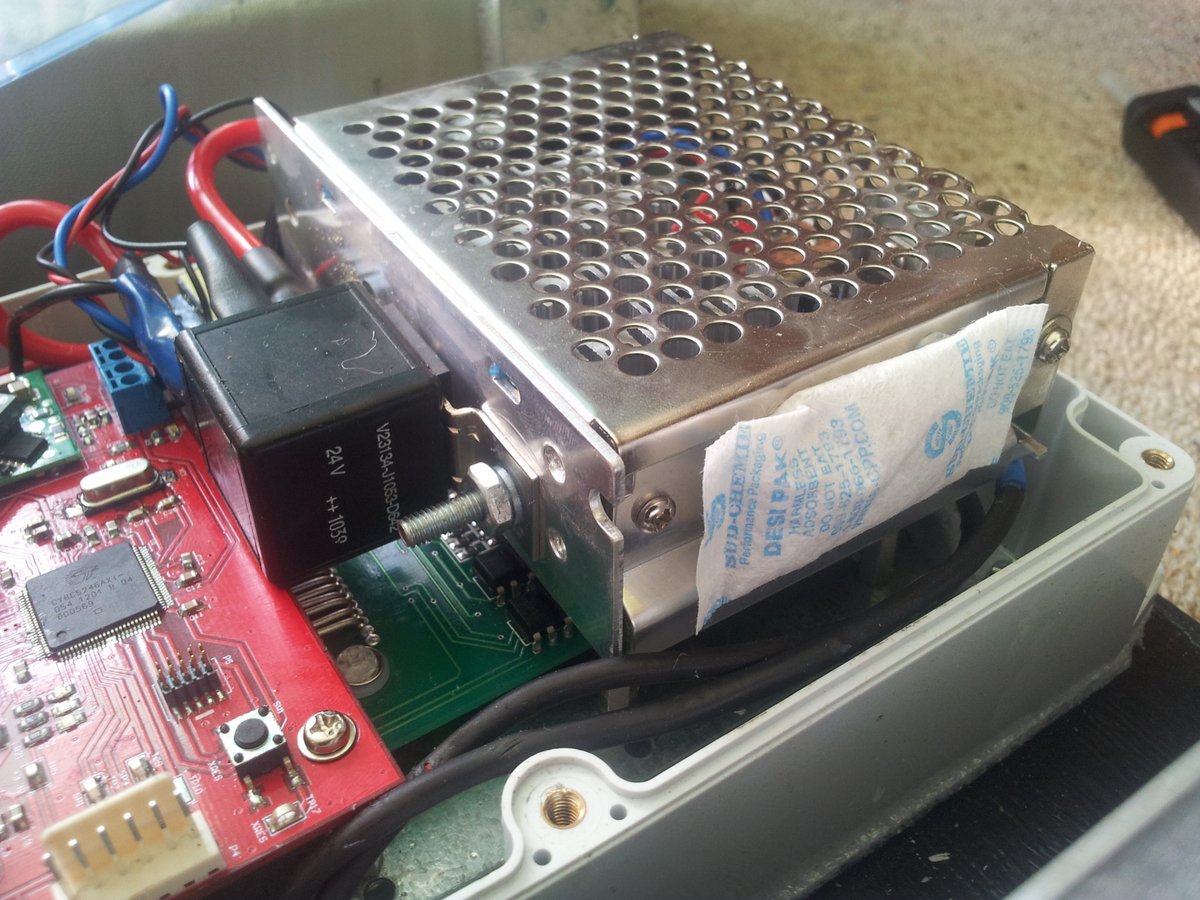
Desiccant
After a few longer test drives, I noticed a bit of moisture condensing on the insides of the enclosure. So I added some desiccant to the skateboard enclosure to absorb any trapped moisture. Find out more about desiccant here.
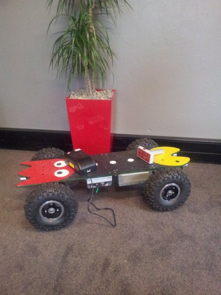
The Finished Electric Skateboard!
A mug shot of the finished board next to some greenery :-D.
And here is a shot of it at night with the lights on.
The underside of the finished electric skateboard.
Weigh-In
Fibreglass Board = 2.84kg Front Truck + It’s 2 Wheels = 4.68kg Back Truck + Motor + It’s 2 Wheels = 8.84kg Tires = 1.42kg (each)
Timesheet
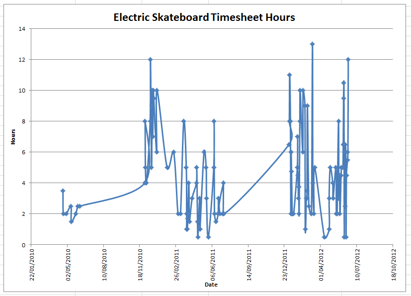
I kept a timesheet because I thought it would be interesting to see how much time was spent on the project. This following graph shows the days and the number of hours in that day that I spent I working on the skateboard.
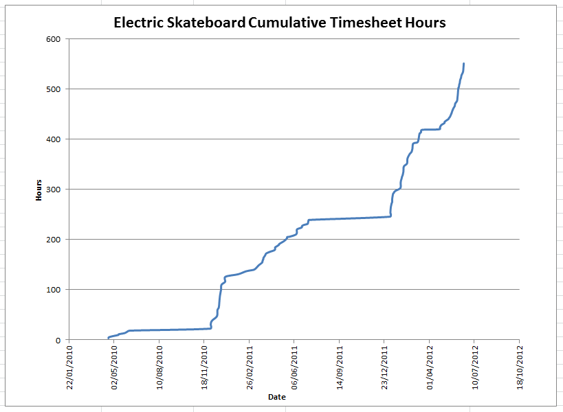
The following graph is the number of cumulative hours.
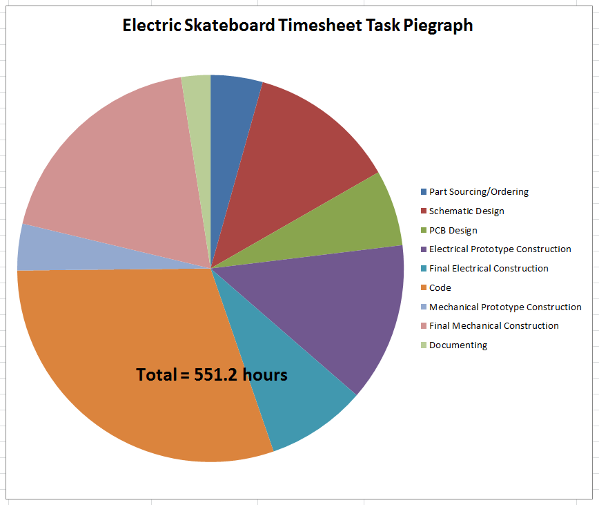
And this is a pie graph showing the proportional amount of time I spent on each “task” or category.


