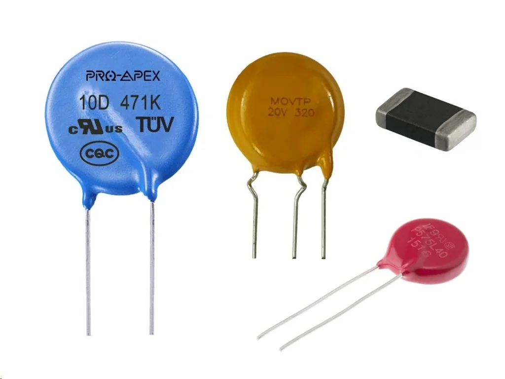
Varistors (VDRs)

A varistor (also known as a voltage-dependent resistor, VDR) is an electrical component whose resistance depends on the applied voltage. As the voltage increases, the resistance of a varistor drops. Their voltage-resistance behaviour is similar to that of a diode, except a varistor exhibits this behaviour with voltages of both polarities (where diodes are a one-way device). They are similar to TVS diodes and gas discharge tubes (GDTs).
They can also be called MOVs, but is strictly a type of varistor named after it’s inclusion of a metal-oxide chemical. Older, silicon carbon (SiC) based varistors are not MOVs, whilst newer zinc oxides (ZnO) ones are. Today most are made from metal oxides.
They are commonly used as a form of circuit-protection against voltage transients, especially in mains and other high voltage applications. For more information about their use for ESD protection, see the ESD Protection page.
Because their resistance in not fixed, they are called non-Ohmic devices.
Schematic Symbol and Designators
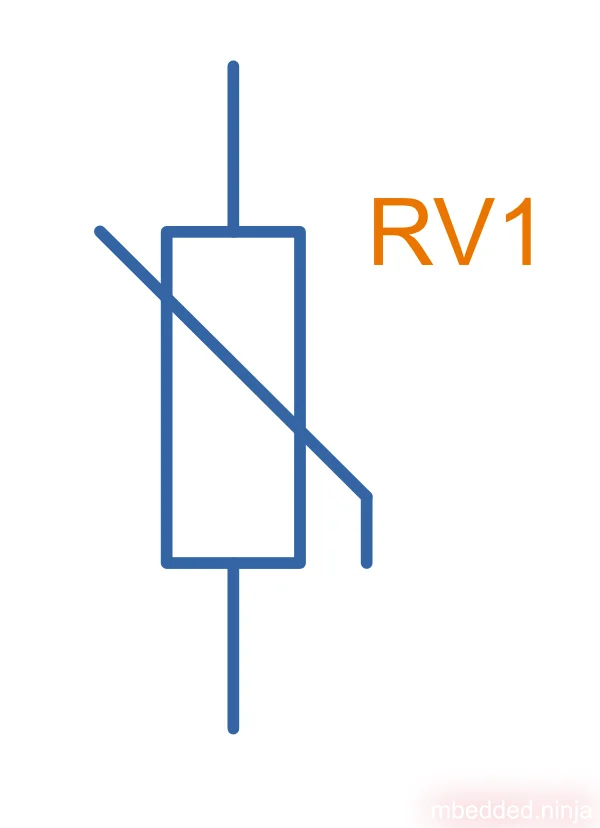
Common designators used for varistors:
RV(my preferred choice)MVMOV
How MOVs Work
Zinc oxide varistors are made from a sintered matrix of zinc oxide (ZnO) grains with other metal oxide additives, sandwiched between two metal plates which act as the electrodes.1 The zinc oxide grains themselves are highly conductive, while the filler material between the zinc oxide grains is highly resistive. A unique phenomenon occurs at the boundary between two zinc oxide grains. Here, depletion regions form and creates what can be considered as back-to-back zener diodes (using zinc oxide, they have a breakdown voltage of around 3.5V).1 Because the grains are randomly orientated and positioned throughout the varistor, the whole structure can be compared a huge network of diodes connected in various series and parallel configurations (and random polarities)2.
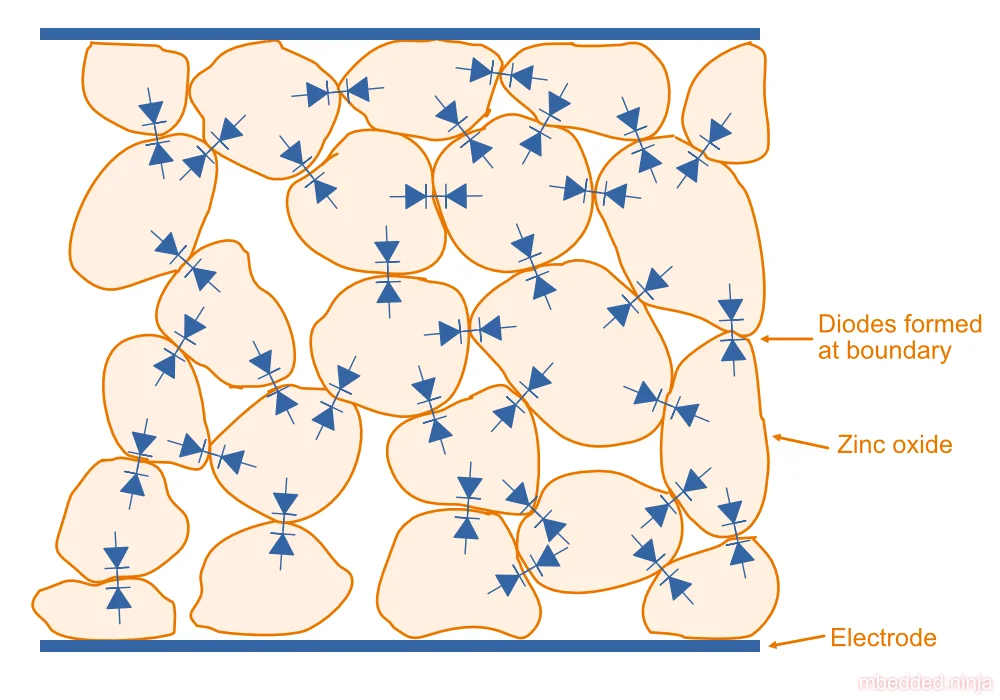
This diode superstructure blocks current until a certain voltage, above which point the diodes begin to cross their breakdown voltage and conduct. The resistance of the varistor drops significantly after this point and large amounts of current can flow. This results in the entire varistor acting as a “shunt” and clamping the voltage across it to a safe level during a voltage surge.
The benefit of having many small zener diodes arranged both in series and parallel over a single Zener/TVS diode is that the energy dissipation is spread out over the entire volume of the varistor, rather than being concentrated around the small junction region in a single diode. This is one of the properties which makes MOVs suitable for high-energy transient protection.1
In the “normal” varistor region of operation (above the leakage current region and below the upturn region), the voltage and current through the varistor is approximated well by the following equation4:
where:
is the current, in Amps
is a constant
is the varistor voltage, in Volts
is a device specific constant (more on this below)
is a “figure of merit” and device specific. The higher the for more non-linear the varistor, and the better it performs as a voltage clamp. It has a very strong relationship to the composition of the device, and can be somewhat generalized by device makeup:
| Composition | |
|---|---|
| SiC (silicon carbide) | 3-7 |
| ZnO (zinc oxide) | 20-50 |
Varistors degrade when they are subjected to repeated surges. This is one downside of varistors compared to TVS diodes, which do not degrade.
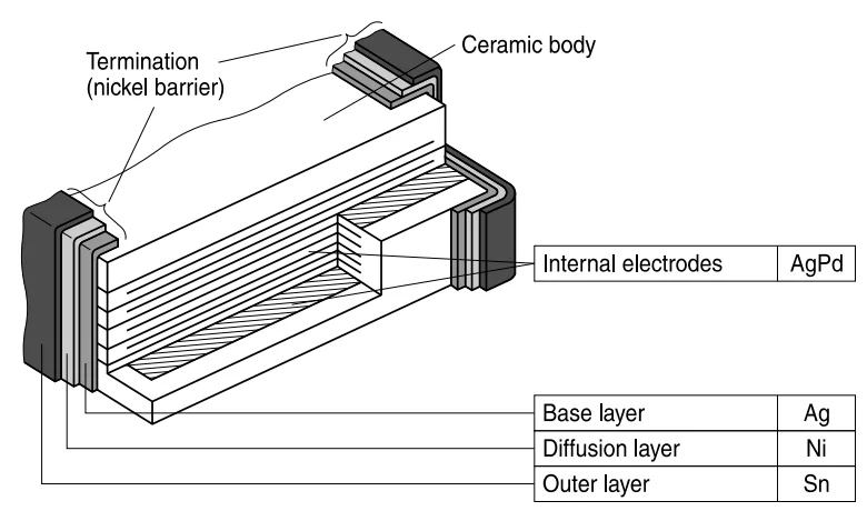
Multilayer Varistors
Multilayer varistors have not one but multiple layers of metal oxide. They are typically manufactured into a SMD chip package such as the 0402 and 0603 sizes (imperial).
Important Parameters
Varistor Voltage
This is the voltage at which the varistor starts to “conduct”. The varistor is considered conducting when the current through it exceeds some small threshold amperage (typically 1mA).
Surge Current
The surge current rating is an indication of how much current the varistor can withstand during a voltage transient event.
Energy Rating
Typically a one-off (non-repetitive) and repetitive pulse energy rating is given for the varistor. The ratings are normally given for standardised transients, such as the 8/10 or 10/1000.
Comparison With Other Forms Of Circuit Protection
TVS diodes are another common form of over-voltage protection used on circuit boards. They behave in a similar manner to varistors in that their resistance drops as the voltage across them increases. MOVs generally have higher power ratings than TVS diodes. However, TVS diodes can be manufactured to provide much lower clamping voltages (3-12 V) compared to MOVs (which are typically rated for 100-500 V, although you can get low voltage (3-50 V) versions). MOVs degrade with repeated over-voltage events, but TVS diodes do not.
This is a placeholder for the reference: tbl-tvs-vs-movs has a comparison of TVS diodes and MOVs.
| Feature | TVS | MOV |
| Surge Capability | Ok | Great |
| Typical Clamping Voltages | 3-400 V | 3-500 V |
| Degradation | No | Yes |
| Size | Small | Large (but this does allow them to handle high energies) |
| Capacitance | Low/moderate | High (typically 100-2,500 pF) |
MOVs may be used in tandem with TVS diodes to provide even better protection against over-voltage transients then any one solution alone.
Further Reading
TVS Diodes are a lower power alternative (or complement) to a MOV. Gas Discharge Tubes (GDTs) are a higher power but less precise alternative to a MOV.
Footnotes
-
TDK (Jan 2018). SIOV metal oxide varistors - General technical information. Retrieved 2025-10-02, from https://www.tdk-electronics.tdk.com/download/531268/8954d4a78154a9da5c70a7119fa03e86/siov-general.pdf. ↩ ↩2 ↩3
-
EEPower. Chapter 3 - Resistor types: Varistor. Retrieved 2021-07-11, from https://eepower.com/resistor-guide/resistor-types/varistor/# ↩
-
Jak Electronics (2021, Jun 13). Metal Oxide Varistor (MOV) Overview: Working and Application. Retrieved 2025-10-02, from https://www.jakelectronics.com/blog/metal-oxide-varistor-mov-overview-working-and-application. ↩
-
Littelfuse. (1999, July). Littelfuse Varistors - Basic Properties, Terminology and Theory. Retrieved 2021-07-11, from https://www.littelfuse.com/~/media/electronics_technical/application_notes/varistors/littelfuse_varistors_basic_properties_terminology_and_theory_application_note.pdf ↩
-
TDK (2025, Jan 29). CTVS - Ceramic transient voltage suppressors - SMD multilayer varistors (MLVs), automotive E series. Retrieved 2025-10-02, from https://www.tdk-electronics.tdk.com/inf/75/db/CTVS_14/Automotive_series.pdf. ↩