Silicon Controlled Rectifiers (SCRs)

A silicon controlled rectifier, or SCR, is an electrical semiconductor which is part of the thyristor family. A SCR is made up of 4 alternating layers of P-type and N-type semiconductor.

It is argued whether an SCR and thyristor are identical or represent two different devices. Those who believe they are two different devices argue that SCRs are thyristors which have a least four layers of alternating p and n-type silicon1. This site always refers to a four-layer thyristor when talking about SCRs. Other parts that are part of the thyristor family that are NOT SCRs include:
- Gate turn-off thyristor (GTO)
- Insulated-gate Bipolar Transistor (IGBT)
An SCR can be turned on electrically via the gate, just like a normal transistor, but cannot be turned off as easily. Once turned on, the SCR latches on, even if the gate voltage is removed. It only turns off when the current through the SCR drops below the holding current, and then a sufficient reverse voltage is applied to a fixed length of time2. The process of turning a SCR off is called commutation.
Schematic Symbol
The schematic symbol for an SCR is shown below:

Commutation
Commutation is the process of the SCR turning itself off. To turn a SCR off, you must do the following:
- Reduce the forward current to below it’s holding current.
- Apply a sufficient reverse voltage for a fixed amount of time.
It’s important to understand that just reducing the SCR’s current to below the holding current is not sufficient. This is because charge carriers (holes and electrons) still exist in the P and N substrates. If, after reducing the current to below the holding current, a positive forward voltage is immediately re-applied to the SCR, it will begin to conduct again.
This is why a reverse voltage has to be applied for at least the minimum off time. This reverse voltage removes the charge carries and puts the SCR back into it’s off state.
There are different ways to achieve commutation which are described below.
Natural Commutation
Natural commutation occurs when an SCR is connected to an AC voltage source (such as 110/240VAC). Because AC contains alternating voltages and currents, the SCR will turn off by itself at the end of the positive half-cycle of the AC waveform.
Natural commutation is also called source commutation, line commutation, or class F commutation.
Class A Commutation
Class A commutation involves using an under-damped RLC circuit as the load. Because of the oscillatory nature of the under-damped RLC circuit, the voltage across the SCR can be forced negative, turning the SCR off. Class A commutation is a form of forced commutation.
Class B Commutation
Class B commutation is when a series LC circuit is connected across the SCR. Class B commutation is a form of forced commutation.
Class C Commutation
Class C commutation is when a second SCR is connected in parallel with primary SCR which is switching the load. Class C commutation is also known as complementary commutation. Class C commutation is a form of forced commutation.
Latch-up
Parasitic SCRs are formed during the manufacturing of CMOS logic devices (e.g. a CMOS totem-pole output driver circuit) on the silicon substrate. These parasitic SCRs can cause the dangerous phenomenon known as latch-up, which can destroy ICs and circuits. Read more about it on the Logic Families page.
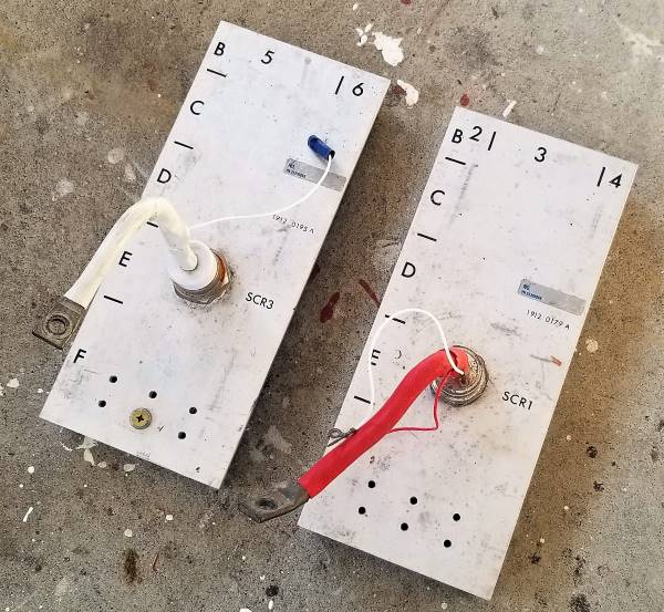
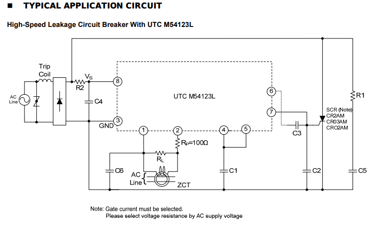
Applications
SCRs are typically used in applications that require the switching of high voltages and/or currents.
They are used in coil-gun/rail-gun designs to connect the charged capacitor bank into the coil or rail, dumping the energy into the gun and firing the device. The typical high voltage and pulse current ratings of SCRs makes them a good choice for this. The main disadvantage of using an SCR over an IGBT for this purpose is that you cannot turn them off. This is not so important in a rail-gun, but in a coil-gun design you may want to disconnect the capacitor bank once the projectile reaches the center of the coil, to prevent pull-back.