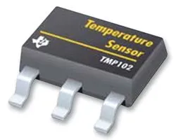
Temperature Sensors
Temperature sensors are electronic transducers which measure the temperature of the nearby body (which in many cases is the temperature sensor itself) and then converts it into either a analogue or digital electrical signal.
Linear Active Temperature Sensors
Linear active temperature sensors output a analogue voltage which is proportional (linear) to the temperature, and require a voltage supply to run.
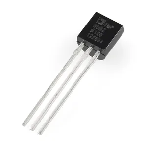
They require contact with the medium that is to be measured. They usually require three connections (power, ground, and ), but can be purchased in packages with more pins. They use an internal diode to measure the temperature, surrounded by circuitry which linearises the output, provides an offset, and makes the reading insensitive to other parameter changes.
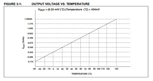
Being encapsulated in a standard through-hole or surface mount component package, these temperature sensors are designed to measure the temperature at the location at which they are soldered onto the circuit board. This is called local temperature sensing. This makes them somewhat unsuitable if you want to measure the temperature of an off-PCB location (remote temperature sensing), although you can mount the through-hole versions onto pretty much anything you want and then attach it to the PCB via a cable. The Texas Instruments LM35DT temperature sensor is one of the last commonly available sensors in a TO-220 package.
This type of temperature sensor is one of the easiest to interface with a microcontroller in an embedded system, since the output can be directly connected to an ADC input, voltage read, and then converted into a temperature by a simple linear equation. They usually output a change of 10 or 19.5mV per degree Celsius, which provides 1bit per degree on a 8-bit ADC with a reference voltage of either 2.5V or 5.0V respectively.
TIP: When looking at the accuracy, be careful, as they usually advertise the typical accuracy, but it is normally the worst case accuracy that is more important to the PCB designer. Sometimes the stated accuracy is only achievable after calibration.
NTC Thermistors
A negative-temperature coefficient (NTC) thermistor can be used as a temperature sensor. A NTC thermistor is a resistor which has a non-linear change in resistance in a response to a change in temperature. It is a passive sensor.

NTCs vs RTDs
A NTC differs from a resistive temperature detector (RTD) in the material used to make the sensor. RTDs have a resistive element made with pure metals, while NTCs have a resistive element made from ceramics or polymers with semiconductor properties.
NTCs are used for smaller, but more accurate temperature ranges such as measuring ambient temperature or fridge/freezer temperature, while RTDs are used for larger, less accurate temperature ranges such as measuring furnace temperature.
Temperature Accuracy
The temperature accuracy of a thermistor can be calculated (at the reference temperature) by dividing the percentage resistance tolerance at 25°C (or whatever the reference temperature is) by the thermistor’s temperature coefficient, .
For example, the Vishay NTCALUG03A103GC has a resistance tolerance of and . Therefore:
Self Heating
A NTC thermistor, like any other resistor, dissipates energy as heat when current flows through it. The power dissipation, in a NTC thermistor is:
where:
is the current going through the thermistor, in Amps
is the resistance of the thermistor, at the present temperature, in Ohms
is the power dissipation as heat in the NTC thermistor, in Watts
Because the resistance of the NTC changes as the temperature changes, so does the dissipated power. In a simple resister divider circuit, the thermistor dissipates the most power when it’s resistance is equal to the fixed resistance.
Beta Equation
The Beta equation or Beta formula is a empirical equation used to work out the temperature from the measured resistance of a NTC thermistor.
It uses a single material constant, , which is also known as the coefficient of temperature sensitivity. The equation is an exponential approximation of the relationship between resistance and temperature in the form:
where:
is the actual resistance, in Ohms, at the actual temperature
is the reference resistance, in Ohms, at the reference temperature
is the actual temperature, in Kelvin
is the reference temperature, in Kelvin
At best, the accuracy of the Beta equation approaches between , and not more than other the NTC thermistor’s entire temperature range.
can be calculated when you have both the temperature and resistance of the thermistor at two different operating points. can be calculated as follows:
Or, written another way:
Re-arranged so that we can calculate a temperature from a measured resistance, and using the terminology and instead of and , we get the following equation:
The free embedded-engineering calculator app, NinjaCalc, features a calculator for working out the thermistor temperature (or any other variable) using the Beta equation.
Steinhart-Hart Equation
The Steinhart-Hart is a complex but highly accurate way of modelling the relationship between temperature and resistance of a NTC thermistor.
The Steinhart-Hart equation is:
where:
is the temperature, in Kelvins
is the resistance at , in Ohms
are the Steinhart-Hart coefficients which vary depending on the type of thermistor and the temperature range of interest
Linearising The NTC With Extra Resistors
By just adding a few extra resistors, the output of a NTC thermistor can be “linearised” enough that the equation can be used within the microcontroller over a limited temperature range.
Linearisation is also used in purely analogue circuits in where there is no digital circuitry (that means no ADCs or processing logic), and the output of the NTC thermistor circuit goes directly to a voltage comparator (or similar) to control an output.
Digital Temperature Sensors
Digital temperature sensors are not as easy to interface with a microcontroller, but offer other advantages, such as the ability to be added onto an existing communication bus (and hence requiring to extra pins to the microcontroller), less sensitivity to noise (you are now transmitting a digital signal, not an analogue one), and the ability to chain many together (temperature sensors using the I2C or 1-Wire interface commonly allow for this).
Digital temperature sensors require contact with the medium that is to be measured.
History
The first every temperature sensor IC was the Texas Instruments LM3911 in 1970.
Sequence Detect
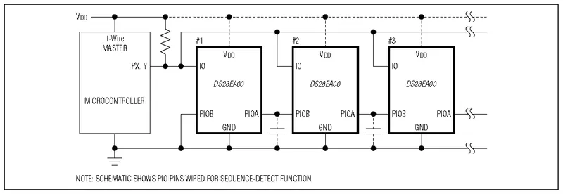
Because it is common to want to string many temperature sensors together to get temperature profiles of large objects (e.g. rooms, buildings, chimneys, pipes, …) you can get temperature sensors which support sequence detect. This allows a microcontroller to determine the position of each sensor in a daisy chain, without requiring a manually entered look-up table (LUT). They normally also use the 1-wire interface, making them very easy to string together. The DS28EA00 “1-wire digital thermometer with sequence detect and PIO” from Dallas is one example. Below is a typical application circuit for this temperature sensor.
Thermostats
Thermostats are simple on/off switched that are controlled by temperature. They are used in cheap, simple, bang-bang temperature control, and the huge benefit with these is that they don’t require a microcontroller or other logic device to control them. The KSD301 is a common code for a family of thermostats with varying temperature ratings.
Infrared Thermopiles
Infrared thermopiles can measure the temperature of an object without coming into contact with it. They measure the amount of incoming infrared radiation, which is related to the temperature of the object. You can by them in IC packages for directly mounting onto a PCB. The ICs normally come with interface electronics, so that you communicate and read the temperature back over a serial communications protocol such as I2C. One example is the TI TMP006.
Thermocouples
A thermocouple is a temperature sensor that is built from two dissimilar metals that connect together at a junction. The thermocouple generates a voltage proportional a temperature difference between the junction and the other end of the thermocouple due to the Seebeck Effect. This voltage can be measured and used to calculate the relative difference in temperature of the junction.
This is a placeholder for the reference: tbl-thermocouple-types shows the different types of thermocouples and their material composition. Sorted alphabetically by type.
| Type | + Lead Material | - Lead Material | ANSI MC 96.1 Color | IEC 584-3 Color | Temperature Range |
|---|---|---|---|---|---|
| Type B | Pt 30%, Rh | Pt | n/a | Grey (+), White (-) | 0°C to +1820°C |
| Type E | NiCr | CuNi | Purple (+), Red (-) | Purple (+), White (-) | -270°C to +1000°C |
| Type J | Fe | CuNi | White (+), Red (-) | Black (+), White (-) | -210°C to +1200°C |
| Type K | NiCr | NiAl | Yellow (+), Red (-) | Green (+), White (-) | -270°C to +1372°C |
| Type N | NiCrSi | NiSiMg | Orange (+), Red (-) | Pink (+), White (-) | -270°C to +1300°C |
| Type R | Pt 13%, Rh | Pt | n/a | Orange (+), White (-) | -50°C to +1768°C |
| Type S | Pt 10%, Rh | Pt | n/a | Orange (+), White (-) | -50°C to +1768°C |
Material legend:
- CrAl: Chromium-Aluminium, Chromel-Alumel
- Cu: Copper
- CuNi: Copper-Nickel, Constantan
- Fe: Iron
- Pt: Platinum
- NiAl: Nickel-Aluminium, Alumel
- NiCr: Nickel-Chromium, Chromel
- NiCrSi: Nickel-Chromium-Silicon, Nicrosil
- NiSiMg: Nickel-Silicon-Magnesium, Nisil
- Rh: Rhodium
IEC 584-3 always uses white for the negative lead.
Fine Gauge Thermocouples
This is a placeholder for the reference: fig-annotated-fine-gauge-thermocouple-rs-pro-397-1573 shows a fine gauge thermocouple. The wires are extremely thin and hard to see in the photo. The brown rectangle is a backing sheet used to protect the thermocouple during storage and transport. The circular dots are just stickers holding the thermocouple to the backing sheet.

Thermocouple ICs
Thermocouple ICs are chips that interface with a thermocouple and provide a useful signal for a microcontroller. Some are “cold-junction compensated”, which means they measure the temperature of the cold junction (inside the IC) with a absolute temperature sensor such as a thermistor, and use that to automatically convert the relative measurement from the thermocouple into an absolute temperature.
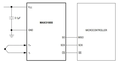
Mineral Insulated Thermocouples
Mineral insulated thermocouples are thermocouples that are enclosed in a thin flexible thin-walled tube/sheath, and insulated from the tube by a compacted mineral powder such as magnesium oxide (MgO). They are significantly more robust than a plain thermocouple that has exposed wires and junction. The magnesium oxide provides good thermal conductivity to the thermocouple.4

Connectors
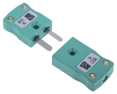
Many thermocouples are connected with a flat 2 pin connector. The connector is typically green or yellow in colour. There is a “miniature” version of this connector which is smaller.
Composite Sensors
Temperature sensors are so ubiquitous that they are often integrated into other sensor ICs to create composite sensors. They are also very useful in helping to calibrate the measurement of another sensor reading, as many real-world measurements dependent on the temperature.
One such example would be humidity sensors.
Footnotes
-
Blaze Technical Services, Inc. Types of Thermocouples with Temperature Ranges & Color Codes. Retrieved 2025-09-09, from https://blazeprobes.com/industry-news-blog/types-thermocouples-temperature-ranges-color-codes/. ↩
-
RS Pro. 397-1573 - Type ‘K’ Fine Gauge Bare Wire Thermocouple [datasheet]. Retrieved 2025-09-09, from https://docs.rs-online.com/8e7f/0900766b815bb282.pdf. ↩
-
Analog Devices. MAX31855 - Cold Junction Compensated Thermocouple-to-Digital Converter [datasheet]. Retrieved 2025-09-09, from https://www.analog.com/media/en/technical-documentation/data-sheets/max31855.pdf. ↩
-
Jumo. Mineral-insulated thermocouples. Retrieved 2025-09-09, from https://en.jumo.de/web/products/apps/productdetailpage?pdpId=901230. ↩
-
RS Pro. 804-7956 - Mineral-insulated K-type Thermocouple with Connector [datasheet]. Retrieved 2025-09-09, from https://docs.rs-online.com/5996/A700000006480198.pdf. ↩
-
RS Pro. 455-9786 - RS PRO Miniature Thermocouple Connector for Use with Type K Thermocouple, 4mm Probe, IEC, RoHS Compliant Standard [product page]. Retrieved 2025-09-09, from https://int.rsdelivers.com/product/rs-pro/rs-pro-miniature-thermocouple-connector-for-use-k/4559786. ↩


