Phototransistors
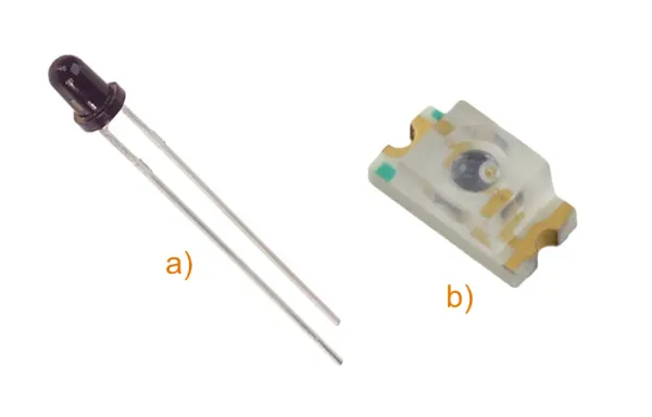
Phototransistors are transistors which can be used to detect light. They are similar to photodiodes, but are more sensitive (i.e. have a higher output current for a given amount of light). Their downside is that they have a slower response time compared to photodiodes.

Schematic Symbol
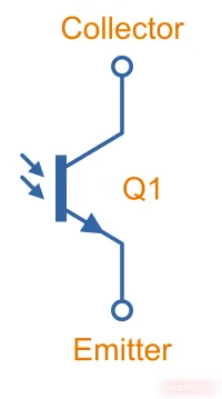
The basic phototransistor schematic symbol is shown in This is a placeholder for the reference: basic-phototransistor-schematic-symbol.
Notice that it looks very similar to the BJT schematic symbol, except the base pin is replaced with arrows indicating it is light-sensitive (the same style of arrows that point away from LED symbols to indicate they emit light).
How They Work
A phototransistor is a BJT but with the base driven from a light-sensitive photodiode rather than electrically from another part of the circuit.
The base-collector junction of a phototransistor is exposed to light (usually via a transparent window on the package). When photos hit the base-collector junction (in the depletion region), they create electron-hole pairs. The generated current is passed through the base to the emitter. The transistor amplifies this base-to-emitter current due to it’s current gain , creating a much larger collector-to-emitter current.
If the emitter pin of a phototransistor is not used, the connection from the base to collector acts just like a photodiode3.
Important Parameters
Collector Dark Current (I_CEO)
- Symbol:
The collector dark current is the current that flows through the collector-emitter junction when no light is shining on the phototransistor. It is typically around 100nA4. If you are attaching a resistor to the phototransistor, make sure the resistance isn’t so high that the dark current causes a significant voltage drop across it.
Collector Light Current (I_CA)
- Symbol:
The collector light current is the current that flows through the collector-emitter junction when a set amount of light shines on the phototransistor. It is typically in the range of and is specified at a particular light irradiance (), light wavelength (), and collector-emitter voltage ( in ).
You can compare collector light currents to get some idea of the phototransistor’s sensitivity.
For example, the Vishay VEMT2000X01 has an of (typical) at , , and 5.
Circuits
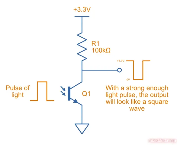
One of the most basic phototransistor circuits can be made simply with a phototransistor and a resistor, as shown in This is a placeholder for the reference: basic-phototransistor-circuit. Under no or low light conditions, the phototransistor is off (save for the dark current) and the output will be pulled high by resistor . When light shines on the phototransistor, it turns on and the output will be pulled to ground by the phototransistor. With a strong enough light source, the phototransistor will saturate and the output voltage will look like a square wave. This is useful for digital circuits (i.e. you can feed this pin directly into a microcontroller GPIO and read it digitally).
Sometimes you won’t have such a nice on/off light source to deal with, and will want to measure varying degrees of light intensity. To do this, you can route the output of this circuit to a microcontroller’s ADC and measure the analogue voltage.
Resistor sets the gain of the phototransistor. The larger the resistor, the larger the voltage drop across it for a given current through the phototransistor. A higher resistance means a higher gain (increased sensitivity to light), but also increases the noise and results in the circuit saturating (the output getting to about 0V) at a lower light level. Choosing an appropriate value for is normally a case of trial and error until you find the right balance between sensitivity, noise, and saturation level.
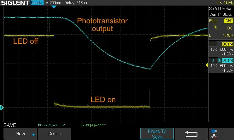
This is a placeholder for the reference: phototransistor-response-to-led shows the response of a Wurth Electronics 1541201NC3060 phototransistor to a light source. The yellow trace represents the LED control signal, where HIGH is OFF and LOW is ON. The blue trace represents the phototransistor output. is . The horizontal time grid is per division, so this is a short pulse. You can see the phototransistor output taking time to respond. This is due to the parasitic capacitance on the output and the low drive strength of the phototransistor. If we left the LED on, the output would eventually settle.
Applications
Phototransistors are used in a variety of applications, including:
- Optocouplers: They are a core component in a optocoupler, used on the receiving side to detect the light emitted by the LED on the transmitting side.
- Detecting environmental light levels.
- Presence detection.
Suppliers
Footnotes
-
DigiKey. Product Index > Sensors, Transducers > Optical Sensors > Phototransistors > Lite-On Inc. LTR-4206E [product page]. Retrieved 2024-09-25, from https://www.digikey.com/en/products/detail/liteon/LTR-4206E/121710. ↩
-
DigiKey. Product Index > Sensors, Transducers > Optical Sensors > Phototransistors > Everlight Electronics Co Ltd PT11-21C/L41/TR8 [product page]. Retrieved 2024-09-25, from https://www.digikey.com/en/products/detail/everlight-electronics-co-ltd/PT11-21C-L41-TR8/2675867. ↩
-
Wikipedia (2024, Sep 2). Photodiode. Retrieved 2024-09-25, from https://en.wikipedia.org/wiki/Photodiode. ↩
-
Lite-On Inc. IR Emitter and Detector - LTR-4206E [datasheet]. Retrieved 2024-09-25, from https://optoelectronics.liteon.com/upload/download/DS-50-92-0073/R4206E.pdf. ↩
-
Vishay Semiconductors. VEMT2000X01, VEMT2020X01 - Silicon NPN Phototransistor [datasheet]. Retrieved 2024-09-25, from https://www.vishay.com/docs/81595/vemt2000x01.pdf. ↩


