Accelerometers

Accelerometers are that measure their acceleration.
Many IC based accelerators are MEMS (micro electro-mechanical devices). These are normally 3-axis devices that return a reading for the x, y and z axis accelerations.
See the IMU page for monolithic components which include accelerometers with other MEMS sensors.
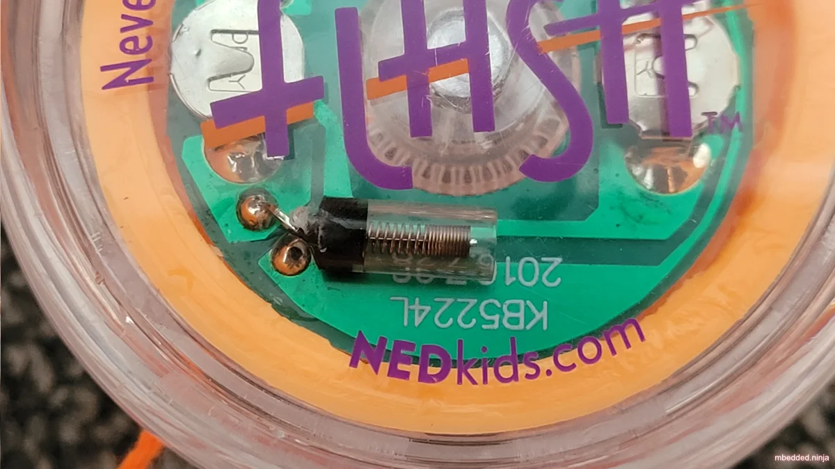
Spring Accelerometers
A soft spring with a metal rod going through the middle of it can act as a really basic accelerometer. These are often called vibration or shock sensors. Then the device is subject to enough acceleration in a direction perpendicular to the spring axis, the spring will bend enough to make contact with the conductive rod and close the circuit.
MEMS Accelerometers
They way MEMS sensors are constructed is quite interesting. Here is a description of the internal MEMS sensor from the ST Microelectronics LIS2DH12 datasheet:
A proprietary process is used to create a surface micromachined accelerometer. The technology processes suspended silicon structures which are attached to the substrate in a few points called anchors and are free to move in the direction of the sensed acceleration. To be compatible with traditional packaging techniques, a cap is placed on top of the sensing element to avoid blocking the moving parts during the molding phase of the plastic encapsulation.
When an acceleration is applied to the sensor, the proof mass displaces from its nominal position, causing an imbalance in the capacitive half-bridge. This imbalance is measured using charge integration in response to a voltage pulse applied to the capacitor. At steady state the nominal value of the capacitors are a few pF and when an acceleration is applied, the maximum variation of the capacitive load is in the fF range. — ST Microelectronics LIS2DH12 datasheet1:
PCB Mounting
Like gyroscopes and magnetometers, accelerometers have to be orientated precisely on a PCB to return accurate readings. Luckily, most SMD packages used these days for accelerometers (such as the QFN and LGA package) have nice self-aligning properties during the reflow soldering process (partly due to the surface tension of the solder paste).
Examples
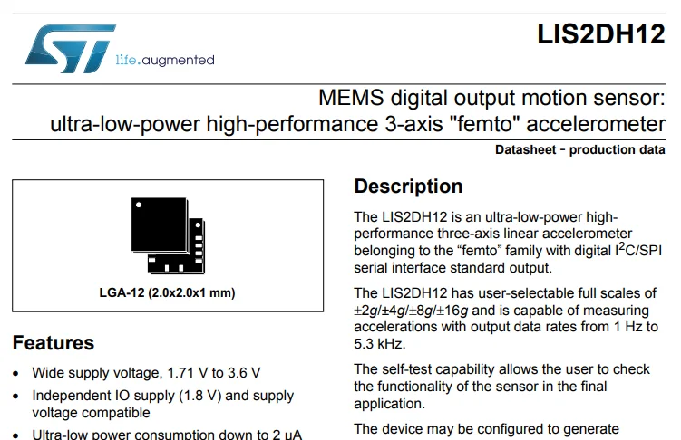
ST Microelectronics LIS2DH12
The ST Microelectronics LIS2DH12 is a “ultra-low power” 3-axis accelerometer. It’s unique selling point is that it can consume just 2 uA of current at 2.5V with a 1 Hz sampling rate. It has ±2g/±4g/±8g/±16g selectable full scale ranges and can communicate via a SPI or I2C interface. It is available in a LGA-12 package.1
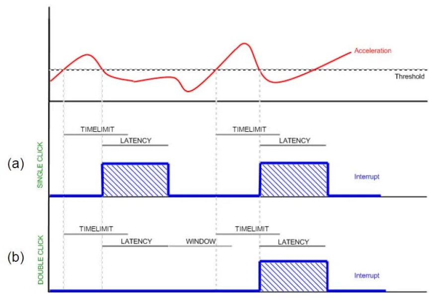
The datasheet for the LIS2DH12 does not describe how the various interrupt types (e.g. THRESHOLD_1, THRESHOLD_2, and CLICK) work. Better descriptions can be found in the LIS3DH: MEMS digital output motion sensor ultra-low-power high-performance 3-axis “nano” accelerometer application note.2 The CLICK detection works by looking for acceleration that goes above a certain threshold then drops again within a specified time window. There is support for “single” click and “double” click detection.
The LIS2DH12 also has a high-pass filter which can be used to remove the DC component of the signal. This can be useful to remove the effects of gravity. It has a adjustable cutoff frequency which can be set from 0.002 to 100 Hz depending on the register configuration and the sampling rate.2
Footnotes
-
ST Microelectronics (2017, May). LIS2DH12 - MEMS digital output motion sensor: ultra-low-power high-performance 3-axis “femto” accelerometer [datasheet]. Retrieved 2025-11-17, from https://www.st.com/resource/en/datasheet/lis2dh12.pdf. ↩ ↩2 ↩3
-
ST Microelectronics (2017, Jun). LIS3DH: MEMS digital output motion sensor ultra-low-power high-performance 3-axis “nano” accelerometer [application note]. Retrieved 2025-11-26, from https://www.st.com/resource/en/application_note/cd00290365.pdf. ↩ ↩2 ↩3