Mechanical Relays
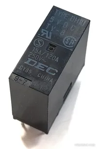
Mechanical relays are electronic components which can switch a load on and off from an isolated control signal using an electromagnet and contactors.
Relays are used for things such as:
- Turing on mains voltage devices from 5-12V circuits, while providing isolation
- Switching large currents
- Providing isolation between two circuits (although opto-couplers are normally used for this)
Relays can also come packaged with other functionality such as built-in timers.
Terminology/Parameters
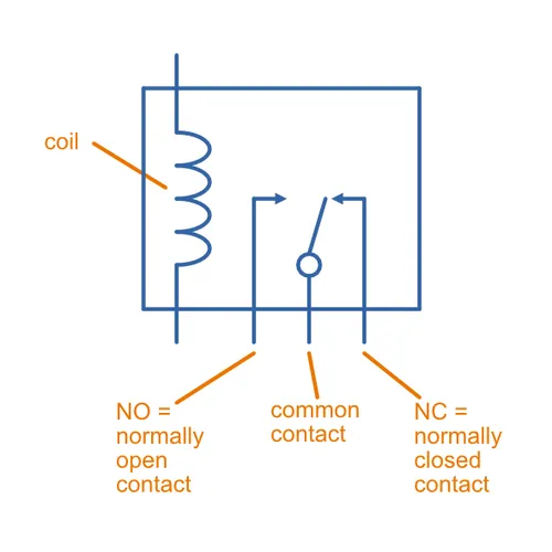
- The Coil: The windings which turn the relay on when you apply a voltage
- The Contacts: The output pins when get connected or disconnected when the relay turns on
- Rated Coil Voltage: The recommended voltage that should be applied to the coil to turn the relay on.
- Rated Coil Current: The current the relay coil will draw when the rated coil voltage is applied to it.
- Contact Current Rating: The maximum current that the relay can conduct through the contacts
Must Operate and Must Release Voltage
The must operate voltage is the minimum voltage that is guaranteed to activate the relay. You should make sure to drive the relay with a voltage that is higher than this when you want to activate the relay. For example, a relay rated at 12 VDC will typically have a must operate voltage of around 9 VDC.
The must release voltage is the maximum voltage that is guaranteed to deactivate the relay. You should make sure to drive the relay with a voltage that is lower than this (or disconnect the coil) when you want to deactivate the relay. For example, a relay rated at 12 VDC will typically have a must release voltage of around 1.2 VDC.
Normal Position of Contacts
The normal position of contacts describes whether contacts are normally open or normally closed when the relay is not energised.
- Normally open (NO): Contacts which are open-circuit when the coil is not energized, and become a short-circuit when the coil is energized. This is probably the most commonly used contact style, although NC is popular also.
- Normally closed (NC): Contacts which are short-circuit to common when the coil is not energized, and become open-circuit when the coil is energized.
Contact Configuration
There are a number of different configurations relay contacts (the output pins) of a relay can have. The National Association of Relay Manufacturers (NARM) (now called the Relay and Switch Industry Association, RSIA) define 23 electrical contact “forms”. These apply to relays, but are used to describe switches. Below are the most common ones that apply to relays:1
- Form A: Contacts are NO and become closed when the relay is energised. Also known as
SP ST NO. - Form B: Contacts are NC and become open when the relay is energised. Also known as
SP ST NC. - Form C: There are three output pins, with a common to one NO and one NC contact. When the relay is energised, the NO contact will be connected to the common and the NC contact will be disconnected from the common. It is performed in a break-before-make sequence (see Form D for the opposite). These are also called
NO-C-NCorSP DT (B-M)relays.1. Can be used as a Form A or Form B relay by ignoring one of the outputs. - Form D: Similar to Form C, but with a make-before-break sequence rather than a break-before-make. This is an uncommon form. Can be abbreviated as
SP DT (M-B). - Form X: Is equivalent to two Form A relays in series, which are mechanically linked and actuated at the same time. Called a double make relay, and can be abbreviated as
SP ST NO DM. These are commonly found in contactors and toggle switches designed to handle high power inductive loads.1 2 - Form Y: Is equivalent to two Form B relays in series, which are mechanically linked and actuated at the same time. Called a double break relay, and can be abbreviated as
SP ST NC DB.2
Many of the forms above are abbreviated into the form <num. poles> <num. contacts> <contact type> <make-break order>. For example, SP ST NO or SP DT (B-M). This comes from the Engineers’Relay Handbook which states:
Sequence of abbreviations. When abbreviations are used to designate a contact assembly, the following order is used: (1) Poles (2) Throws (3) Normal position (4) Double make or break (if applicable). Example: SPST NO DM refers to single pole, single throw, normally open, double make contacts. — Relay and Switch Industry Association (RSIA): Engineers’ Relay Handbook.2
This is a placeholder for the reference: tbl-relay-acronyms summarises the acronyms used.
| Acronym | Description |
|---|---|
| NO | Normally open |
| NC | Normally closed |
| DP | Double pole |
| TP | Triple pole |
| DT | Double throw |
| B | Break |
| M | Make |
| DB | Double break |
| DM | Double make |
This is a placeholder for the reference: fig-relay-contact-forms shows a diagram of the different relay contact forms.
Relays are typically described with the number of these “forms”. For example “1 Form C” or “2 Form A”.
Make-Break Order
The make-break order describes the exact sequence of switching when the relay is activated.
- Break-before-make: The relay will first disconnect the normally-closed (NC) contact before connecting the normally-open (NO) contact.
- Make-before-break: The relay will first connect the normally-open (NO) contact before disconnecting the normally-closed (NC) contact. Thus all contacts will be briefly connected to each other when the relay is energised.
This is a placeholder for the reference: fig-make-break-order shows a diagram of the two different make-break orders a relay can have.
Dry Contacts
It is common in the electrical industry to refer to “wet” or “dry” contacts. In the context of relays, “dry contacts” are normally used. This is when the relay does not provide electrical power to the output contacts. The relay simply switches the contacts together, in the same way a mechanical switch would. It is up to the external circuitry to provide the power to the load. As shown in This is a placeholder for the reference: fig-dry-contacts-relay-schematic, one contact could be connected to 240VAC (or any other voltage), and the other contact to the live of an external load (which already has a neutral connected to it). When the relay is activated, the contacts will be connected together.
It is not clear to me what a “wet” relay contact would be. Potentially this would be if one contact of a NO pair was permanently connected to 240VAC (and not connected to the outside world), with the other contact being available to connect to an external load. When the relay is activated, the available contact would be “energized” to 240VAC and power the load.
Inductive Kickback and Flyback Diodes
The coil of a relay is basically an inductor. Due to the rapid when the relay is switched off, the inductive coil will generate a large negative voltage to try and keep the current flowing (remember: inductors “resist” the change in current). This is called inductive kickback. This voltage spike can cause havoc in neighbouring components (e.g. killing the transistor used to switch the relay on, or arcing across switch terminals) if not suppressed. A flyback diode in anti-parallel across the coil of the relay will clamp the voltage spike to approx. no more than .
It is absolutely necessary to connect a diode in the circuit as a means of preventing damage from the counter emf --- Panasonic: Relay Technical Information3.
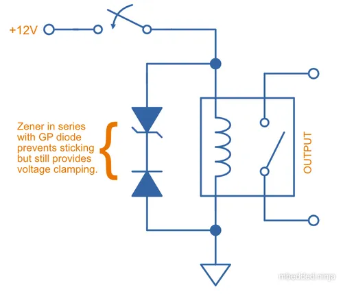
However, there are some drawbacks to using basic flyback diodes. On relay switch-off, the flyback diode decays the magnetic field of the coil far more slowly than if there was no flyback diode protection present. This causes the relay to take longer for the “clapper type” relay contacts to open. When relay contacts open, small “microwelds” occurs at the contact interface. Usually, the contacts are moving apart with enough force/velocity that these welds are easily broken. However, the slower open time with a flyback diode can cause the relay to “stick” — this is when the contacts become welded together and do not open43.
This diode shunt provides maximum protection to the solid state switch, but may have very adverse effects on the switching capability of the relay --- TE Connectivity (Application Note): Coil Suppression Can Reduce Relay Life4.
The solution? Add a Zener diode in series with the general purpose diode to increase the voltage drop when the coil is turning off. This causes the magnetic field to collapse faster (closer to an open-circuit), but still provides circuit protection. Choose a Zener voltage so that the Zener voltage plus forward diode drop does not exceed the maximum voltage of the switching element (or other circuitry).
Contact Voltage and Current Ratings
Relays rated for switching specific voltages and currents through their contacts (the output side of the relay).
You might be wondering why a relay might be rated for a higher current with AC than at DC. Switching AC signals are gentler than DC signals on relays. This is because the voltage and current drops to zero twice per cycle in an AC signal. When you break an AC connection, the arc that forms is typically extinguished at the zero-crossing point. An arc in DC is harder to extinguish as the current flow is constant. This is a placeholder for the reference: fig-cit-j107f-relay-ul-and-tuv-contact-ratings-with-ac-dc-differences-highlighted shows an example of this with the CIT J107F family of relays.

This is a placeholder for the reference: fig-omron-g5le-1-dc24-relay-switching-capacity-and-durability-graphs shows another example, this time it’s from the datasheet of the Omron G5LE-1 DC24 general purpose relay.
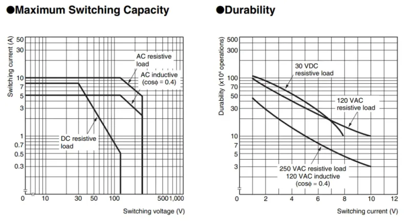
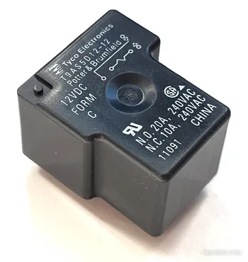
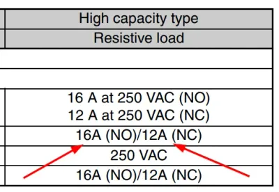
There can also be a different in current rating for a relay which has normally-open and normally-closed contacts. This is due to the contact pressure difference when the contacts are closed. For a normally-open contact, the contacts are held closed by the magnetic force of the relay coil. For a normally-closed contact, the contacts are only held closed by the spring. The force from the coil is much stronger than the spring, as this directly impacts the contact resistance. The contacts held closed by the coil have a lower contact resistance, and can therefore handle more current. This is a placeholder for the reference: fig-omron-g5le-relay-no-vs-nc-current-difference shows an example of this with the Omron G5LE relay family.6
Latching
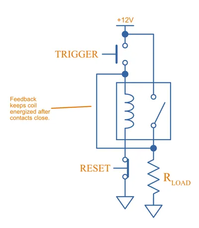
With a little external componentry, a mechanical relay can be made to latch-on after triggered, and will only reset once a reset button has been pushed (or power disconnected).
Enclosure Rating
The enclosure rating is the amount of environment protection the relay has. A common thing to denote is whether or not the relay is sealed. Two common ratings are:
- Flux protection: Not fully sealed, but enclosed enough to prevent any issue with flux. Similar to a RT II rating.
- Sealed: Fully enclosed. Similar to a RT III or higher rating.
If you are planning on submersing a PCB with a relay on it in an ultrasonic bath, make sure you are using a sealed relay. If not, the cleaning solution will more than likely enter the relay and cause damage. It can either cause an immediate fault (i.e. direct short-circuit) or slowly corrode the contacts over months. I have personally experienced this first hand with a product that started failing a few months after it was installed in the field due to it being cleaned ultrasonically. The PCB had a relay on it that was not sealed, and after cutting open a relay on a failed unit, the contacts were seriously corroded.
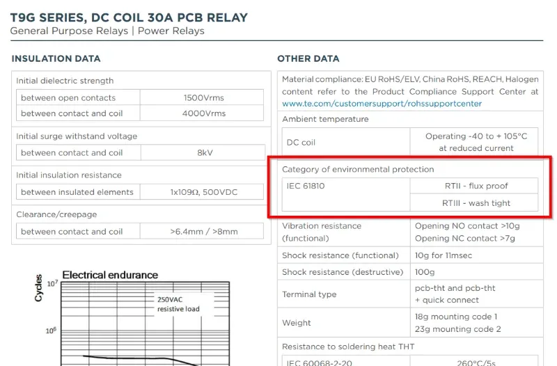
Some relays will use IEC 61810 to denote the enclosure rating. IEC 61810 has the following ratings:7 8
- RT 0: Unenclosed relay. Relay not provided with a protective case.
- RT I: Dust protected relay. Relay provided with a protective case that prevents dust from entering the relay.
- RT II: Flux proof relay. Relay capable of being automatically soldered without allowing flux to enter the relay other than were intended.
- RT III: Wash tight (washable) relay. Relay capable of being automatically soldered and then washed (e.g. ultrasonic bath) without allowing the ingress of flux or washing solution.
- RT IV: Sealed relay. Relay provided with a case that has no venting to the outside, with a time constant better than 2x10^4s in accordance with IEC 60068-2-17.
- RT V: Hermetically sealed relay. Sealed relay having an enhanced level of sealing, with a time constant better than 2x10^6s in accordance with IEC 60068-2-17.
Common Relay Packages
Most PCB mount relays are through-hole components. My guess is that they have not gone SMD like many other components because they are quite bulky and heavy — using SMD pads would probably pose a risk of the pads being ripped of the PCB. Through-hole leads gives much better mechanical strength.
Most PCB-mount relays have an asymmetric lead configuration so that it cannot be installed incorrectly.
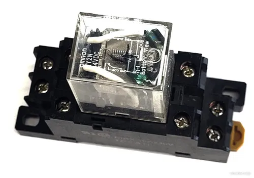
You can get DIN mounted relay “sockets” for mounting relays onto DIN rail, as shown below:
Supplier Links
- DigiKey
- Main relay page: https://www.digikey.com/en/products/category/relays/14
- For “power relays” (over 2A): https://www.digikey.com/en/products/filter/power-relays-over-2-amps/188
- TE: http://www.te.com/catalog/relays/menu/en/16453
Types
Armature Relays
Armature relays are the most common type of mechanical relay. They have a magnetized armature which is moved by the magnetic field of the coil (electromagnet). The contacts are connected to the armature and make or break the output circuit. Armature relays are more popular than reed relays, primarily due to the higher current carrying capabilities. They are also more resistant to external magnetic fields. However, they are slower to switch and cannot handle very high voltages like reed relays.
Reed Relays
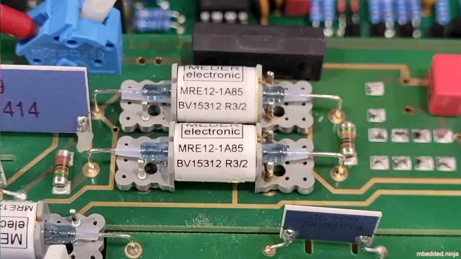
Reed relays are a type of relay that used an electromagnet to move a reed switch. The contacts in the reed switch are magnetic and the magnetic field directly moves the contacts. This is what distinguishes them from armature relays, which require a armature to move non-magnetic contacts.9
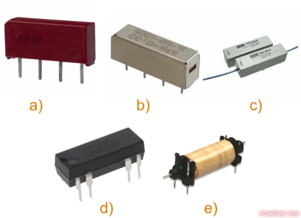
Because they do not have an armature, they can switch much faster because the contacts are very light weight. They also typically require less electrical power to operate. Many reed relays seal the reed switch in a thin and long glass tube to protect the contacts from corrosion.9
Reed relays typically cannot handle as high a current as armature relays (most are rated for 100 mA to 3 A), but can typically handle higher voltages (e.g. 1000-10,000 V) due to the glass sealed environment the contacts operate in.
DigiKey’s reed relays category can be found here.
Product Links
The G5Q/G5LE is a popular range of though-hole PCB mount relays from Omron. The G5Q series can go up to 250VAC at 10A.
Further Reading
- Solid State Relays are the completely electronic equivalent of a mechanical relay with no moving parts.
- Switches can also control loads but are mechanically actuated by the user rather than switched electronically.
- Transistors (e.g. BJTs or MOSFETs) can switch loads like a relay, but are completely electronic and are not isolated from the load.
Footnotes
-
Wikipedia (2024, Sep 16). Electrical contact. Retrieved 2024-12-02, from https://en.wikipedia.org/wiki/Electrical_contact. ↩ ↩2 ↩3
-
Relay and Switch Industry Association (RSIA). Engineers’ Relay Handbook. Retrieved 2024-12-03, from https://web.archive.org/web/20170705143411/http://www.esterline.com/powersystems/DesignReference/RelayHandbook.aspx. ↩ ↩2 ↩3
-
Panasonic. Relay Technical Information. Retrieved 2021-12-29, from https://www.panasonic-electric-works.com/pew/eu/downloads/technical_information_relay_en.pdf. ↩ ↩2
-
TE Connectivity. Application Note: Coil Suppression Can Reduce Relay Life. Retrieved 2021-12-29, from https://www.te.com/commerce/DocumentDelivery/DDEController?Action=srchrtrv&DocNm=13C3264_AppNote&DocType=CS&DocLang=EN. ↩ ↩2
-
Omron. G5LE - PCB Power Relay - Cubic, Single-pole 10A Power Relay [datasheet]. Retrieved 2025-01-16, from https://omronfs.omron.com/en_US/ecb/products/pdf/en-g5le.pdf. ↩ ↩2
-
Durakool. Contact Resistance Vs Contact Pressure. Retrieved 2025-01-16, from https://www.durakool.com/media/5bqpde0s/contact-resistance-vs-contact-pressure.pdf. ↩
-
TE Connectivity (2023, Dec). POTTER & BRUMFIELD - T9G SERIES - DC COIL 30A PCB RELAY - GENERAL PURPOSE RELAYS | POWER RELAYS [datasheet]. Retrieved 2025-02-20, from https://www.te.com/commerce/DocumentDelivery/DDEController?Action=srchrtrv&DocNm=T9G&DocType=Data%20Sheet&DocLang=English&DocFormat=pdf&PartCntxt=CAT-P851-T1. ↩ ↩2
-
TE Connectivity (2018, May). Automotive, General Purpose and Signal Relays - Definitions [technical note]. Retrieved 2025-02-20, from https://www.te.com/commerce/DocumentDelivery/DDEController?Action=srchrtrv&DocNm=Definitions_Relays&DocType=SS&DocLang=EN. ↩
-
Wikipedia (2025, Jul 20). Reed relay. Retrieved 2025-10-06, from https://en.wikipedia.org/wiki/Reed_relay. ↩ ↩2


