Relays

Published On:
Oct 25, 2012
Last Updated:
Sep 11, 2024
This section covers the two main types of relays: mechanical and solid-state. See the child pages for more information.
Child Pages
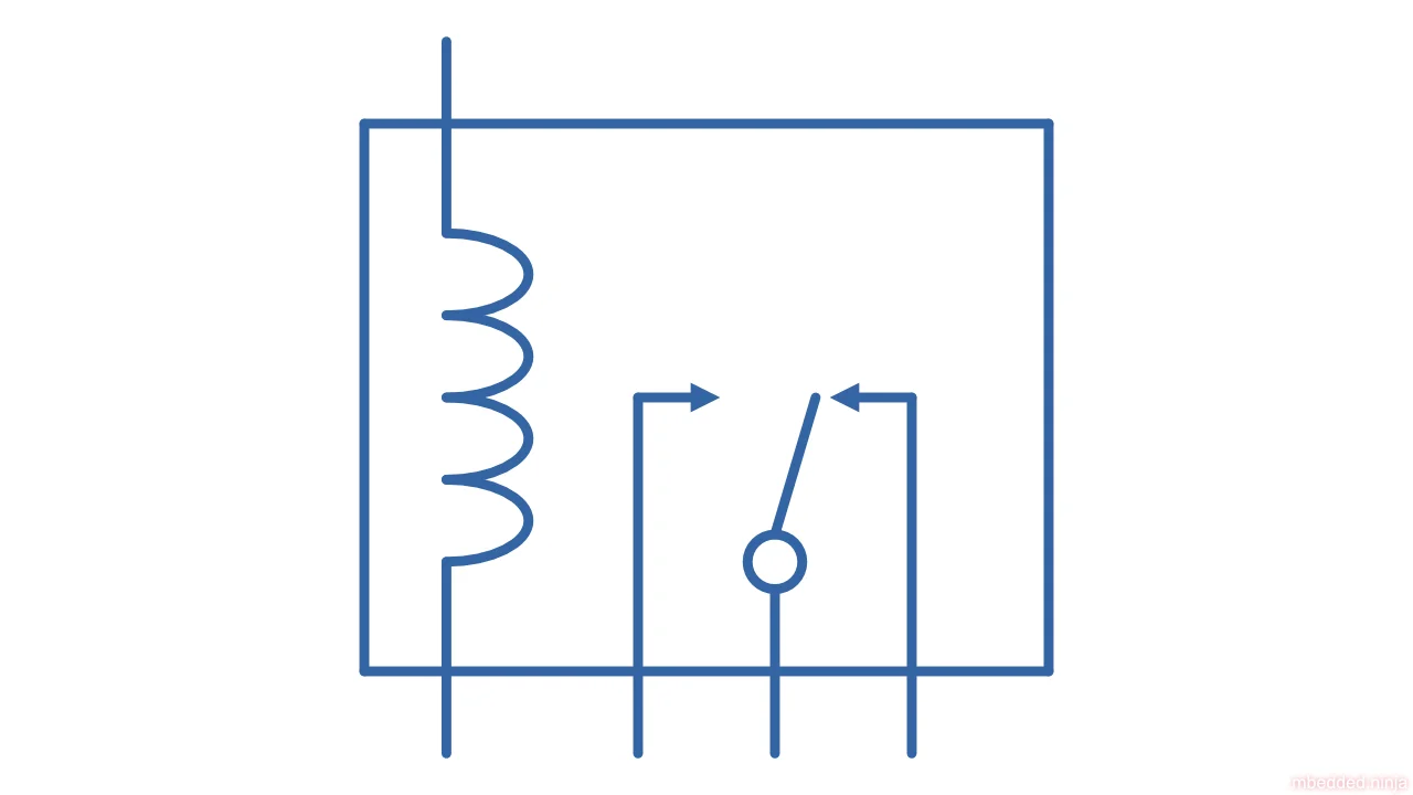
Mechanical relays are electronic components which can switch a load on and off from an isolated control signal using an electromagnet coil and mechanical actuator. This page covers terminology, parameters, contact arrangements, inductive kickback, flyback diodes, latching, common relay packages, supplier links and more.
Mechanical Relays
Mechanical relays are electronic components which can switch a load on and off from an isolated control signal using an electromagnet coil and mechanical actuator. This page covers terminology, parameters, contact arrangements, inductive kickback, flyback diodes, latching, common relay packages, supplier links and more.
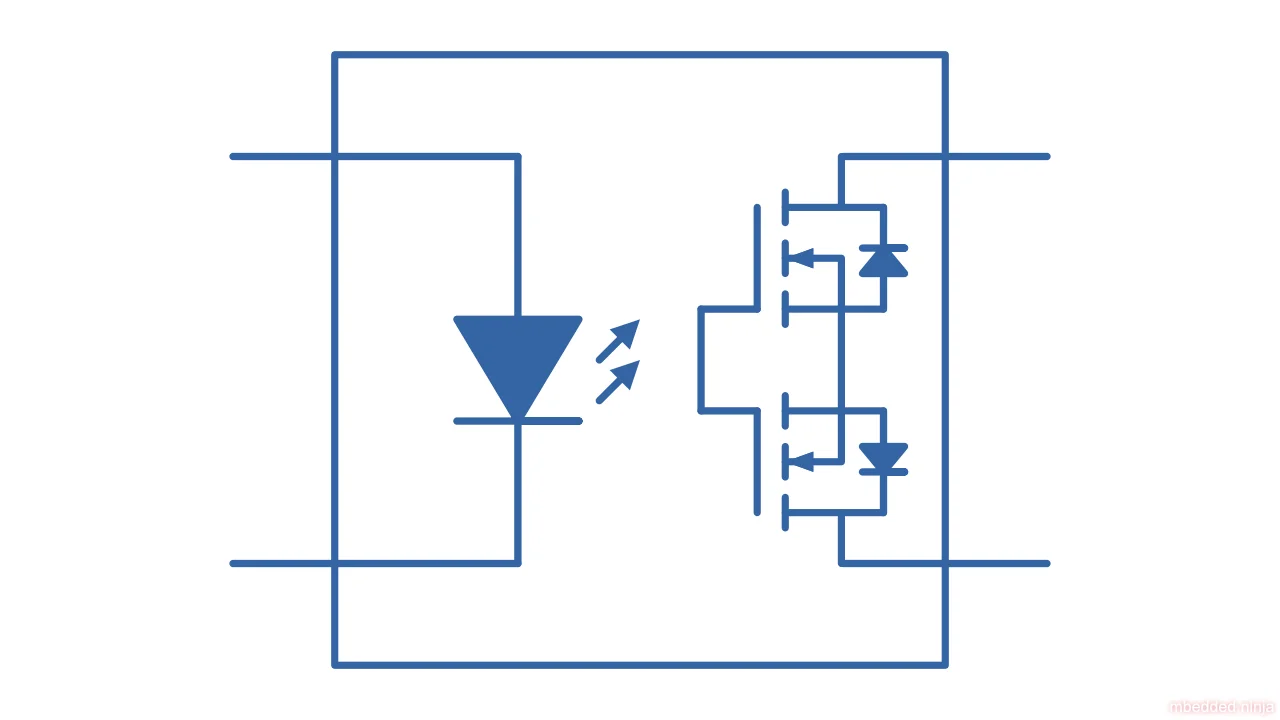
Solid-state relays (SRRs) are relays that use don't have any moving mechanical parts involved in the switching. They use semi-conductor devices (normally MOSFETs) to perform the switching instead.
Solid State Relays (SSRs)
Solid-state relays (SRRs) are relays that use don't have any moving mechanical parts involved in the switching. They use semi-conductor devices (normally MOSFETs) to perform the switching instead.