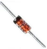
PIN Diodes
A PIN diode is a semiconductor diode with a wide un-doped intrinsic semiconductor region between a p-type and n-type semiconductor region (hence the name PIN).
A “normal” PN diode has a very small intrinsic region, which is good when you wish to use the diode as a standard rectifier. The PIN diodes wide intrinsic region makes it an inferior rectifier, but makes it suitable for1:
- Attenuators
- Fast switches
- Photodetectors (when used in a reversed-biased state)
Important Parameters
Dark Current
- Symbol:
- Units:
Typically in the 0.1-5nA range.
Extinction Ratio
Field of View
- Symbol: FoV
Output Rise Time
- Symbol:
- Units:
Responsivity
- Symbol:
PIN diodes are normally operated in the reverse bias state.
Because of their good light-to-current linearity, they are commonly connected to a transimpedance amplifier (one which converts an input current into an output voltage). A typical example would be the Maxim MAX3658, which is designed for fibre-optic applications.
RF Applications
PIN diodes act as almost perfect resistors in the RF and microwave frequencies1. The resistivity these AC waveforms see is dependent on the DC bias current flowing through the diode, and the intensity, wavelength and modulation rate of the incoming light.
Because the PIN diodes RF resistance is dependant on the DC bias current, they can be used as an RF switch or variable resistor. The RF resistance can range from about to .
Reverse Recovery Time
PIN diodes have a very poor reverse recovery time.
Footnotes
-
Wikipedia. PIN diode. Retrieved 2021-11-25, from https://en.wikipedia.org/wiki/PIN_diode. ↩ ↩2


