LT3745 Design Guide
This is a design guide for the LT3745 LED driver.
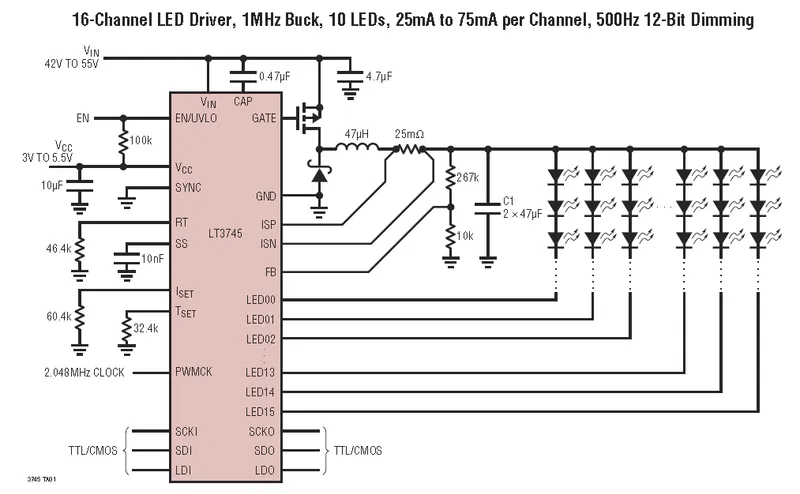
The LT3745 LED driver by Linear Technology is a advanced driver which can individually control the current for up to 16 LED circuits. It features an on-board buck converter (except for the inductor and caps), a current regulator, and 16 PWM modules to fine tune the current for each circuit.

RT And The Switching Frequency
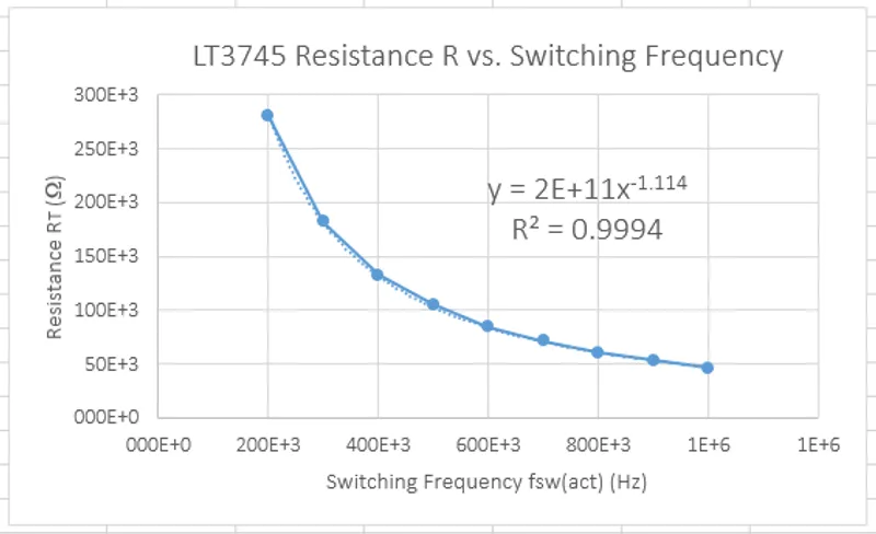
The LT3745 datasheet gives a table of common resistances and the corresponding switching frequency, but it does not give you an equation to work it out. I grabbed the values from the datasheet, plotted them, and fitted a trend-line to get an equation, as shown in the following image (but note, Excel has rounded the co-efficient has been rounded too-much, see the equation again below the image for better accuracy):

The resulting power-based equation is (with better accuracy):
which had a regression coefficient of , not a bad fit!
Be Careful When Probing
It could be said that the LT3745 is poorly designed when it comes to the separation of low and high-voltage pins. The design places +5V logic pins right next to the LED supply line, which can be in excess of +50V. On the small QFN-40 package, this poses a risk if you are probing pins (e.g. with an oscilloscope or multimeter), because you can quite easily fry things if you short the two together.

