Delay Lines
Delay lines are digital ICs which can delay a digital signal by a certain amount of time. They are used for a number of applications, including:
- Signal delay
- HSYNC pulse generation in LCD displays1
How They Work
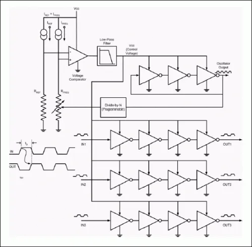
Most delay ICs work by using a chain of inverter gates, along with advanced circuitry to compensate for voltage and temperature variations and keep the delays accurate2. This is a placeholder for the reference: fig-ds1135-internal-circuitry shows the internal circuitry of the Analog Devices DS1135 “3-in-1 Delay Line” IC2.
Delay lines usually have multiple output pins, each which is connected to a different point in the delay sequence. These are called taps. The number of taps is an important parameter of the delay line3.
Delay until first tap, and the incremental delay are also important parameters.
Further Reading
See the Delay Circuits page for a summary of various types of analogue and digital delay circuits.
Footnotes
-
Analog Devices. DS1124 - 5.0V 8-Bit Programmable Timing Element. Retrieved 2024-10-30, from https://www.analog.com/en/products/ds1124.html. ↩
-
Analog Devices (2002, Aug 30). How Delay Lines Work. Retrieved 2024-10-30, from https://www.analog.com/en/resources/technical-articles/how-delay-lines-work.html. ↩ ↩2 ↩3
-
Analog Devices (formerly Dallas Semiconductor/Maxim) (20023, Nov). DS1110L - 3V 10-Tap Silicon Delay Line. Retrieved 2024-10-30, from https://www.analog.com/media/en/technical-documentation/data-sheets/DS1110L-DS1110LE-500.pdf. ↩


