I2S Communication Protocol

Inter-Integrated Circuit (Inter-IC) Sound (I2S) is a synchronous, serial communication protocol which uses Pulse Code Modulation (PCM) to transmit audio data between integrated circuits, typically those within the same PCB. It is commonly used to send audio between electronics such as MCUs, DSPs and audio amplifiers.
It can be written/pronounced as:
- I2S, pronounced “eye-two-ess”.
- I²S, pronounced “eye-squared-ess”.
- IIS, pronounced “eye-eye-ess”.
ICs connected using I2S for audio data transfer will typically also be connected via I2C for control and configuration.
History
I2S was originally developed by Phillips in the 1980s. The first I2S specification was published in 1986, and it was revised in 19962 3.
I2S Signals
There are three signals in the I2S protocol:
- Serial Clock (SCK): This is the clock signal that is used to synchronise the data transfer between the master and slave devices. The clock signal is generated by the master device and is used by the slave device to sample the data.
- Word Select (WS): This signal is used to indicate whether the data being transferred is left-channel, right-channel or a control word. The WS signal is generated by the master device. It is also known as left-right clock (LRCLK)4 or frame sync (FS)5.
- Serial Data (SD): This is the actual audio data that is being transferred between the master and slave devices.
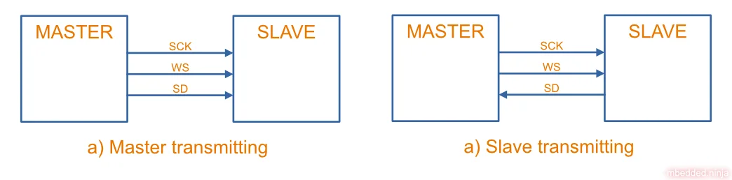
This is a placeholder for the reference: fig-i2s-signals-between-master-and-slave shows the I2S signals required between master and slave devices. In a), the master device (transmitter) is sending data to the slave device (receiver). In b), the slave device (transmitter) is sending data to the master device (receiver).
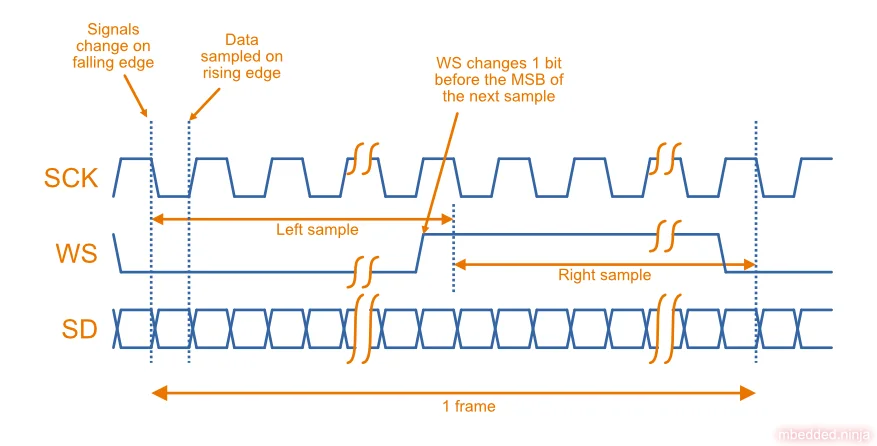
This is a placeholder for the reference: fig-i2s-waveform-diagram shows the digital waveforms of the three I2S signals.
The three signals are explained in more detail below.
Serial Clock (SCK)
The Serial Clock (SCK) signal is used to synchronise the data transfer between the master and slave devices. The clock signal is generated by the master device and is used by the slave device to sample the data.
The SCK frequency is dependent on:
- The number of bits per sample (typically 8, 12, 16 or 24 bits).
- The number of channels (e.g. 2 for left and right audio).
- The audio sample rate (samples per second, commonly ).
For example, for a 16-bit stereo audio signal with a sample rate of 44.1 kHz, the SCK frequency would be:
So even though you typically think of audio as being in the 0-20 kHz range, the digital bitstream that represents the audio can quickly climb into the MHz range. 1-10 MHz is generally not a problem for short traces on a PCB without high-speed design considerations.
SCK runs continuously2.
Word Select (WS)
The Word Select (WS) signal lets the receiver know whether the data being transmitted is for channel 1 (WS = 0) or channel 2 (WS = 1). For stereo signals WS = 0 is used for the left channel and WS = 1 is used for the right channel.
It is important to note that WS changes one clock cycle before the MSB of a sample is transmitted, rather than on the same clock cycle. This is so that a slave transmitter knows to start transmission of the next sample on the next clock cycle. It also allows the receiver to store the previous sample and clear the input ready for the next sample6.
It is also known as left-right clock (LRCLK, LRCK4) or frame sync (FS).
WS is normally synchronized with the falling edge of SCK, and is latched by the receiver on the rising edge.
WS has a 50% duty cycle and has the same frequency as the audio sample rate.
Serial Data (SD)
The Serial Data signal (SD) is used to transmit the audio samples. Data is sent as a signed number in two’s complement format. The most significant byte (MSB) is sent first.
Data may be clocked out by the transmitter on either the rising or falling edge of SCK (usually on the falling edge). However, at the receiver data is always sampled on the rising edge of SCK.62
Master vs. Slave vs. Transmitter vs. Receiver
The Master device is the device which is generating the SCK and WS signals. The Slave is the other device. Master and slave devices can both be either the transmitter or receiver in an I2S connection. The transmitter is the device which is generating the SD signal.
A slave device, not having control of the SCK and WS signals, is normally designed to handle receiving more or less bits per sample that it expects. This allows for two devices with different sample rates to communicate. If the slave device receives more bits than it needs, it can ignore the extra bits (waiting for WS to change) knowing that the bits it has received are the most significant bits. If it receives fewer bits than it needs, it can pad the least significant bits of it’s sample with zeros.
I2S Over Cables
I2S was designed to be run short distances on PCBs. However, some companies have developed ways to run I2S over cables.
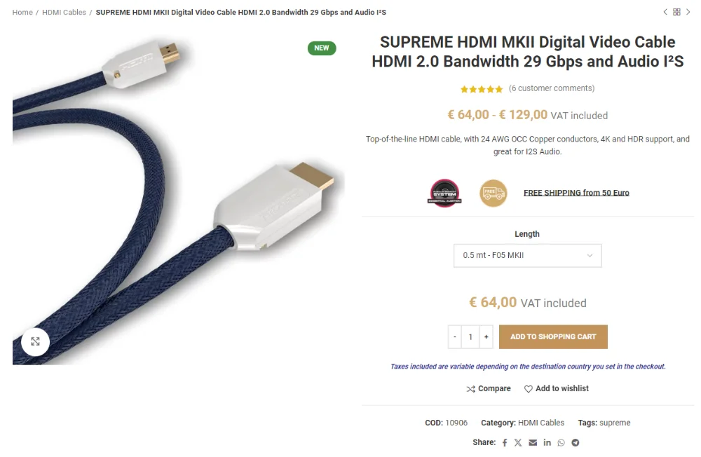
PS Audio started the trend of using I2S over HDMI cables. They use differential I2S signals rather than the single-ended signals used in the formal I2S standard.
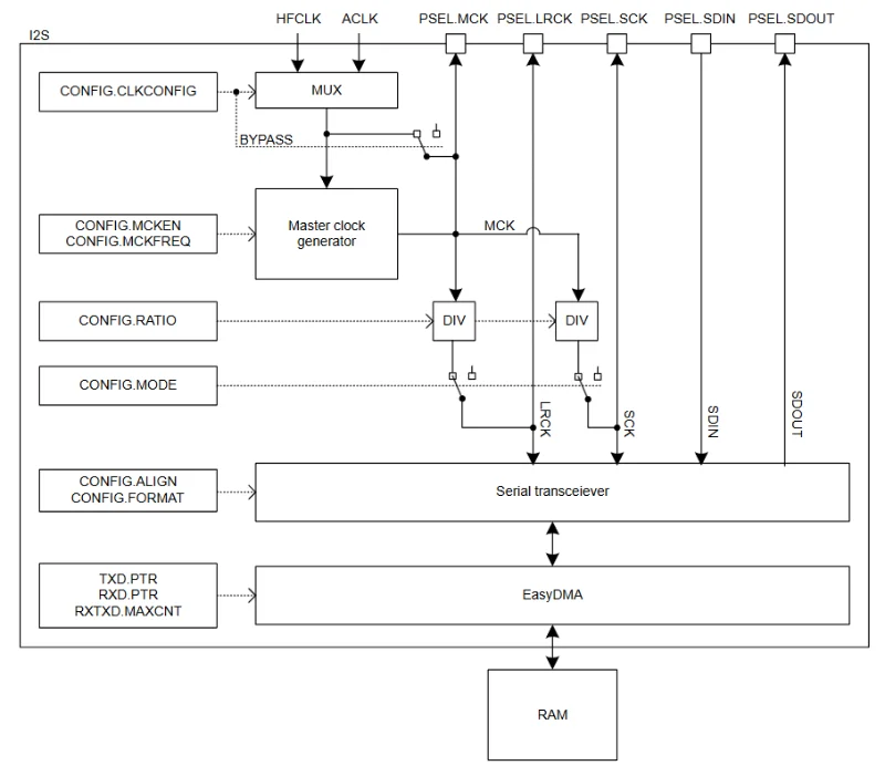
MCU Support
The Nordic nRF52 and nRF53 MCU families have I2S peripherals. These peripherals allow for both the transmission and reception of audio data. They usually support DMA for transferring audio data in and out of memory without CPU intervention.4 The Nordic I2S peripheral supports both the standard “I2S format” and an “aligned format” --- the aligned format is when WS is no longer changes 1 bit before the MSB of the next sample, but rather changes at the same time as the MSB.4
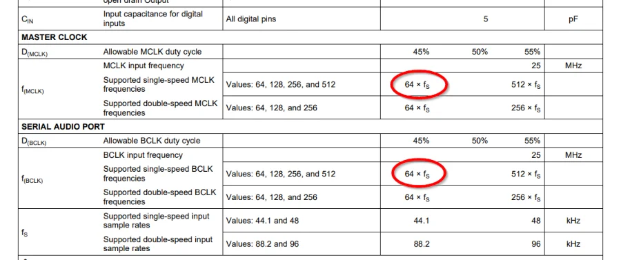
Note that the nRF52 I2S peripheral does not support padding when acting as a master. This means that it does not support audio amplifiers such as the Texas Instruments TAS5720x family which require a MCLK and BCLK that is at least 64 times the audio sample rate.9 These values are shown in This is a placeholder for the reference: fig-ti-i2s-audio-amp-tas5720x-min-clock-freq-highlighted. The problem here is that with BCLK at 64x the sample rate, this means at least 32-bits per left and right channel are required. But the nRF52 I2S peripheral only supports up to 24-bits per sample, and there is no ability to add padding to increase it up to 32-bits.
The nRF53 MCU can support these high clock frequency audio amplifiers because it supports “separate sample and word widths” (as per the nRF53 specifications).8 This is essentially “padding”, and the sample will be either left or right aligned at the start of each half frame.
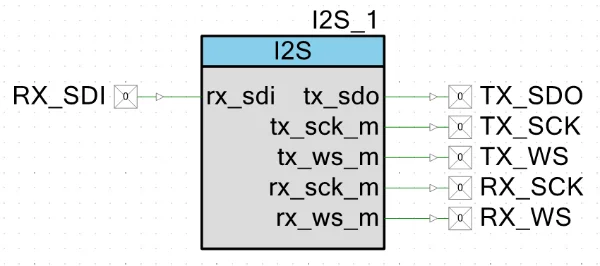
PSoC MCUs support I2S via components in PSoC Creator. The following diagram shows the PSoC “I2S TX Master and RX Master” component in PSoC Creator:
I2S Amplifier ICs
MAX98365
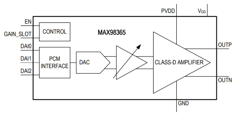
The MAX98365 is a “plug-and-play” digital class-D amplifier that supports I2S. It is “plug-and-play” in the sense that it auto-detects different PCM and TDM clocking schemes and has no I2C configuration required. This means you can typically power it up, provide LRCLK, BCLK and SD and it will work. Given it has no I2C configuration, it does provide a pin called GAIN_SLOT which can be used for gain selection in I2S mode.10
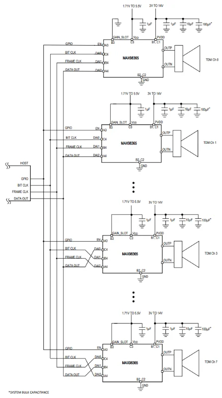
The MAX98365 also supports TDM mode, where up to 8 of the MAX98365s can be connected together with only 4 wires, as shown in This is a placeholder for the reference: fig-max98365-tdm-operation-schematic-8-channels.
Frameworks and Libraries
Zephyr RTOS has an I2S API that can be used to configure and use I2S peripherals on supported MCUs. It also supports non-standard extensions such as PCM short/long frame sync and left/right justified data formats11.
Footnotes
-
Wikimedia Commons. I2S Logo [image]. Retrieved 2024-09-05, from https://commons.wikimedia.org/wiki/File:Logo_i2S.jpg. ↩
-
Robert Keim (2020, Mar 4). Introduction to the I2S Interface. All About Circuits. Retrieved 2024-09-06, from https://www.allaboutcircuits.com/technical-articles/introduction-to-the-i2s-interface/. ↩ ↩2 ↩3
-
Elprocus. I2S Protocol : Working, Differences & Its Applications. Retrieved 2024-09-06, from https://www.elprocus.com/i2s-protocol/. ↩
-
Nordic. nRF52 Series > nRF52832 > nRF52832 Product Specification > I2S — Inter-IC sound interface. Retrieved 2024-09-06, from https://infocenter.nordicsemi.com/index.jsp?topic=%2Fcom.nordic.infocenter.nrf52832.ps.v1.1%2Fi2s.html. ↩ ↩2 ↩3 ↩4
-
Wikipedia. I²S [article]. Retrieved 2024-09-05, from https://en.wikipedia.org/wiki/I%C2%B2S. ↩
-
Phillips Semiconductors (1986, Feb). I2S bus specification. Retrieved 2024-09-07, from https://web.archive.org/web/20070102004400/http://www.nxp.com/acrobat_download/various/I2SBUS.pdf. ↩ ↩2
-
Ricable. SUPREME HDMI MKII Digital Video Cable HDMI 2.0 Bandwidth 29 Gbps and Audio I²S [product page]. Retrieved 2024-09-07, from https://www.ricable.com/en/prodotto/supreme-hdmi-cavo-video-digitale-hdmi-2-0-bandwidth-29-gbps-e-audio-i2s/. ↩
-
Nordic Semiconductor (2024, Jun 27). nRF5340 Product Specification > Peripherals > I2S — Inter-IC sound interface. Retrieved 2024-11-25, from https://docs.nordicsemi.com/bundle/ps_nrf5340/page/i2s.html. ↩ ↩2
-
Texas Instruments (2016, Feb). TAS5720x Digital Input Mono Class-D Audio Amplifier With TDM Support Up To 8 Channels [datasheet]. Retrieved 2024-11-25, from https://www.ti.com/lit/ds/symlink/tas5720l.pdf. ↩ ↩2
-
Analog Devices (2022, Jan). MAX98365 Tiny, Cost-Effective, 14V Plug-and-Play Digital Class-D Amplifier [datasheet]. Retrieved 2024-11-25, from https://www.analog.com/media/en/technical-documentation/data-sheets/MAX98365.pdf. ↩ ↩2 ↩3
-
Zephyr. _Inter-IC Sound (I2S) Bus [documentation]. Retrieved 2024-09-05, from https://docs.zephyrproject.org/latest/hardware/peripherals/audio/i2s.html. ↩