RFID
RFID (radio-frequency identification) is a wireless method of transmitting data between a reader and tag, for the purposes of tracking and identification.
Acronyms
- Auto-ID: Automatic Identification
- EPC: Electronic Product Code
- HF: High Frequency
- ISO: International Standards Organisation
- LF: Low Frequency
- MF: Microwave Frequency
- NFC: Near-field Communication
- RFID: Radio Frequency Identification
- RoHS: Restriction of Hazardous Substances
- SAL: Smart Active Label
- UHF: Ultra-high Frequency
- UPC: Universal Product Code
- WEEE: Waste Electrical And Electronic Equipment
Frequencies
There are four (but three common) frequency bands that RFID uses. Based on knowledge of sound and radio waves, you’d expect lower frequency RFID to achieve longer read distances. But the opposite is true! Higher frequency RFID communications get the longest read ranges.
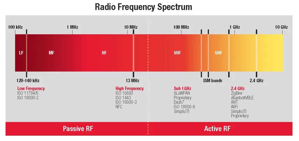
Here is a summary of the four bands:
Low Frequency (LF)
- 125kHz
- Uses the “near-field” effect, utilizing magnetic field coupling rather the electric. Only works for short distances (< 10cm).
High Frequency (HF)
- 13.56MHz
- Typical read range of 1-1.5m
Ultra-high Frequency (UHF)
- Between 868-960MHz
- 1-10m read range (longer read/write range than HF)
- Uses the “far-field” effect
- Contains the largest number of inlay/label products
- Absorbed by water-containing liquids (but not as much as MF RFID)
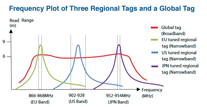
The following graph shows the allowed UHF frequency bands in different countries.
Microwave Frequency (MF)
- 2.4-5.8GHz
- 10-80m read range
- Longest read/write range, but waves are absorbed readily by many materials, including water (it’s the same frequency as microwaves)
- Rare RFID frequency
- MF can also stand for metal-friendly RFID
Power Configurations
Passive
Passive tags have no physical power source and instead get all of their power from the incoming RF signal transmitted by the reader. Passive tags usually don’t have an option for external circuity, as they require to run of extremely low amount of energy. However, there are a few passive chips which provide a single I/O pin, which can be used as an input, output, or either (which is called a GPIO in the embedded world), depending on the chip. This includes the Microchip MCRF202 and Atmel ATA5570, which both operate in the LF band, and the NXP UCODE SL351213FTB0, which operates in the UHF band.
Semi-Active
Semi-active tags have a nearby physical power source, however, they still rely solely on the transmitted energy from the reader to power the communications. The energy from the battery is used to power external circuitry for say, remote monitoring applications. Semi-active tags can be read with readers designed for passive tags.
Active
Active tags are powered with a nearby physical power source, and don’t rely on the energy from the incoming RF signal. For this reason, they can have higher transmit powers, and therefore promote greater transmission distances between tag and reader.
Power Limitations
Regulations normally use one of the two following units to regulate power:
- (equivalent isotropic radiated power). Used mainly in the U.S.A
- (effective radiated power): Used mainly in Europe
Note that the two are related by the following equation:
The free-space path loss equation is also useful for determining the transmission distance behaviour of a RFID system. The free-space path loss equation is:
where:
= free-space path loss (unitless)
= distance between transmitter and receiver (meters)
= signal frequency (Hertz)
= speed of light in a vacuum ()
Readers
Readers are also called interrogators. UHF readers typically have transmit powers from 5-32.5dBm (3-1000mW).
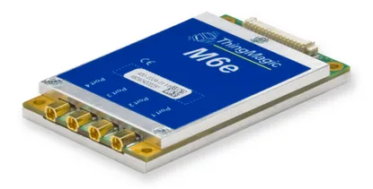
Modules
Reader modules exist for integrating an RFID reader into an OEM product, and are typically around the size of a credit card, and are designed to be mounted on a PCB. Skyetek and Thingmagic make popular UHF RFID modules.
Chips
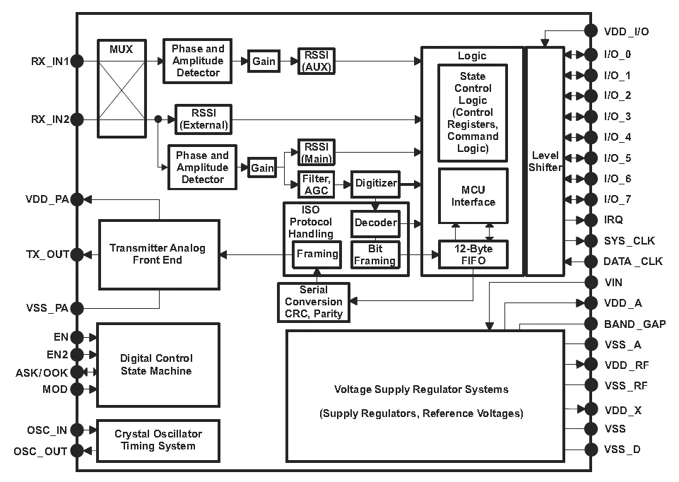
Stand-alone ICs also exist. The following image is the block diagram for the Texas Instruments TRF7960A 13.56MHz RFID transceiver IC. TI provides example C firmware code for this device on both the MSP430 and 32-bit ARM architectures.
Tags
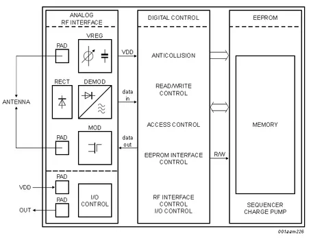
On-metal compatibility of tags is a big issue. Nearby metal objects cause RFID signal reflections that change the received/sent signal. There are special tags that are designed to work when mounted or near metallic objects. In some cases, due to the reflections, they can out-perform non-metallic mounted tags. The typical RFID chip architecture is shown below:
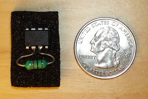
Tags can be made with incredibly basic materials! Once such example is the RFID tag made with just a single AVR ATtiny chip and inductor, as shown in the image below. This is an incredible hack which uses multiple “dirty tricks” to work. Here is a link to the original article by Scanlime.
There are apparel label categories that tags can be certified for, these are:
- A - Denim apparel
- B - Polybagged apparel
- C - Boxed items
- D - Hanging apparel
Passive ICs
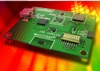
Murata makes a MAGICSTRAP chip, which is a passive RFID device designed to be soldered onto a PCB for circuit board tracking and inventory management. The antenna is etched onto the PCB, and sections of the antenna make up the pads in which the chip is soldered to. It operates in the UHF band, and a 4-6m range is possible.
Inlays/Labels
RFID inlays are a popular way form of cheap, disposable RFID tags. They are usually paper thin, flat, and contain both an embedded RFID chip and flat planar metallic antenna.

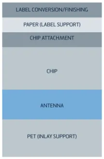
They commonly follow the layer makeup shown below:
Larger inlays give more room the antenna, giving longer read ranges. You can either get “dry” or “wet” inlays. Dry inlays have no adhesive on the back, while wet ones do. The difference between an inlay and a label is pretty ambiguous, but in general, an inlay is just the RFID chip, antenna, and supporting structure, while a label is an inlay coated in printable surface with adhesive on the back. The distance between one inlay and another also effects the read distance. There are special inlay-style tags that are suitable for when the tags are stacked within millimeters of one another.
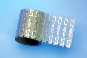
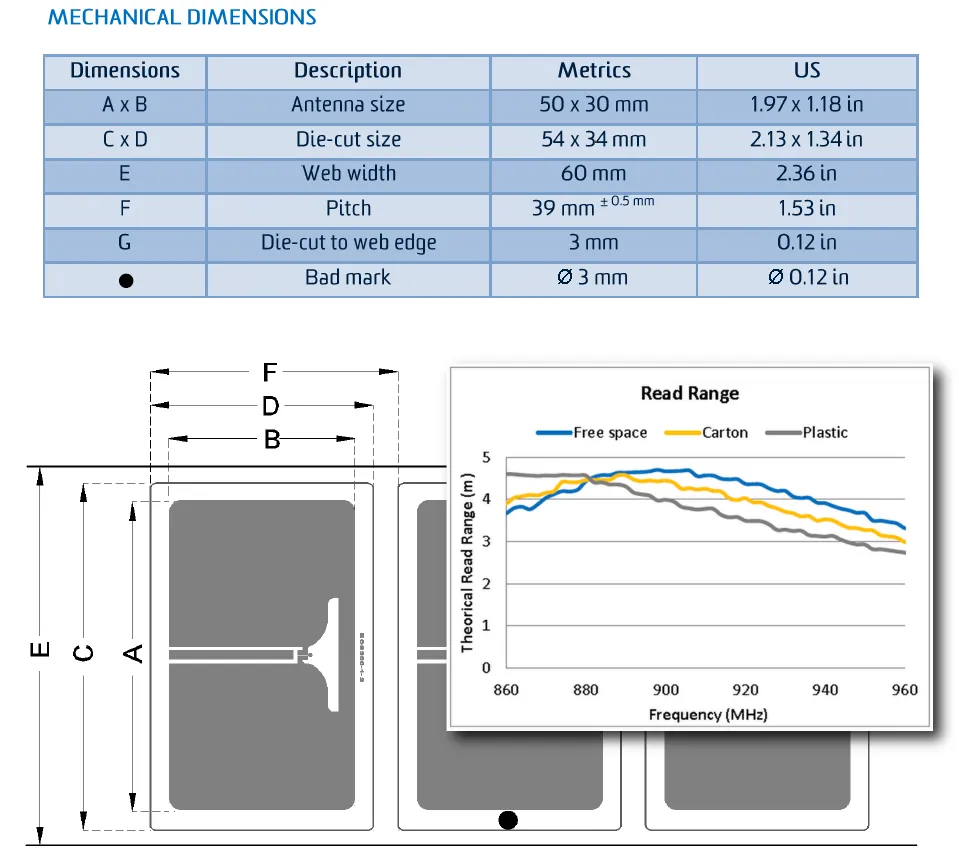
The following image shows the dimensions of a typical inlay (the Tageos EOS-300), along with a graph of the measured read distances when it is attached to a number of different materials.
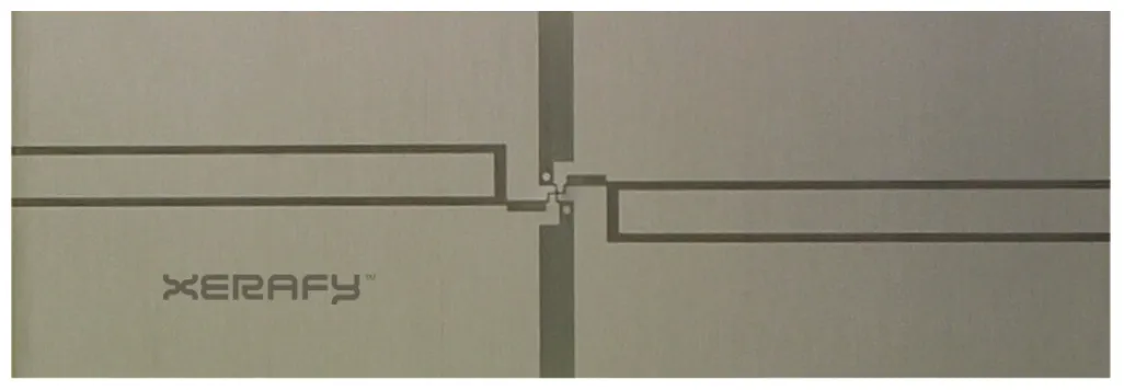
A few select manufacturers make metal-capable UHF RFID inlays. As of 2012, they are still quite rare (as opposed to metal-capable tags, which there are more of). The following is a image of the Xerafy metal-capable UHF inlay.
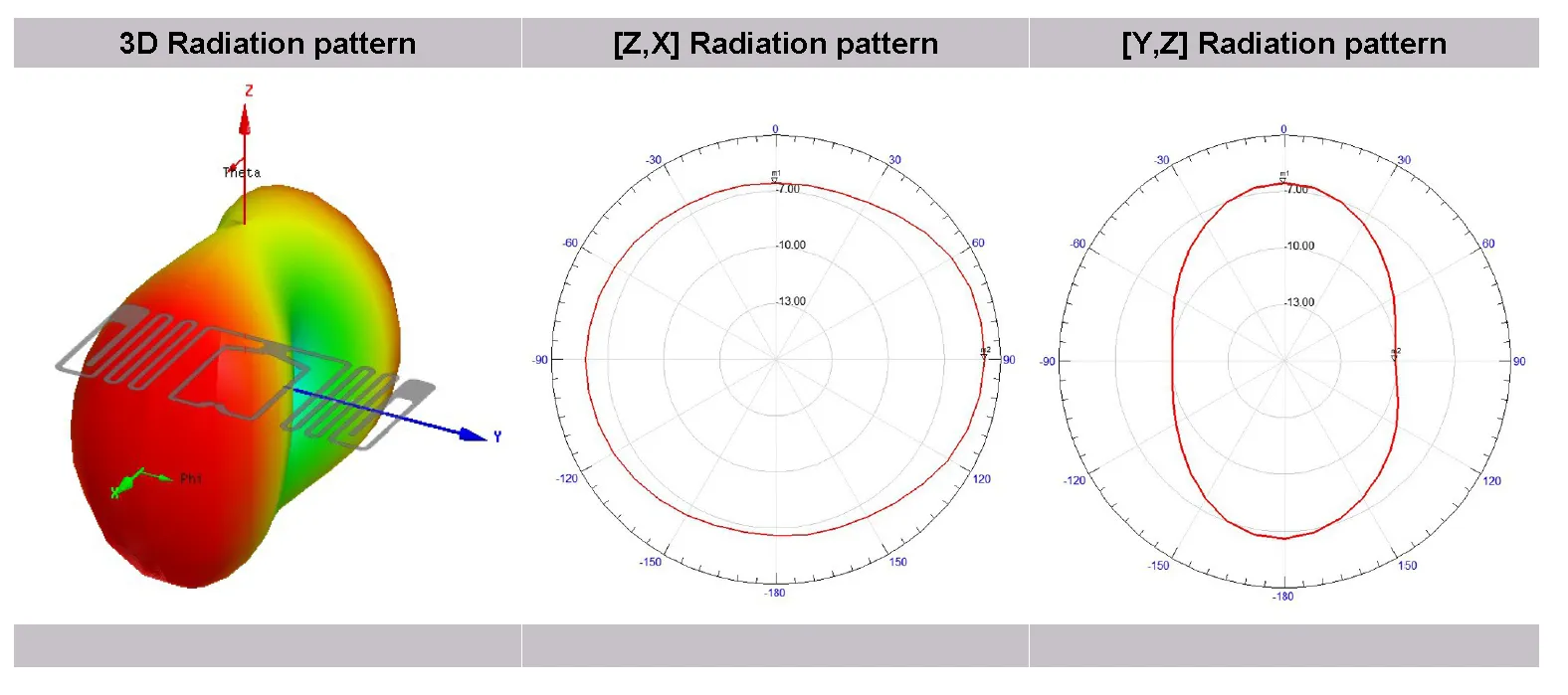
The following image shows a typical radiation pattern from an RFID inlay.
Cables
RFID tags exist which use wire cables for their antennas. They normally look like a piece of wire (about 150mm long for a UHF version), with a piece of heatshrink in the middle. Compared to solid tags and inlays, they have the benefit of being very flexible and thin.
Metal Compatible
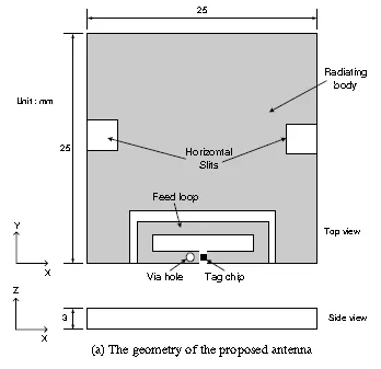
Specialized tags/inlays exist for attaching/putting in close proximity to metal in where a normal tags range would be greatly limited/not work at all. They are normally more expensive than the standard RFID products. Xerafy makes a range of these metal-compatible tags/inlays. The article “Small Proximity Coupled Ceramic Patch Antenna For UHF RFID Tag Mountable On Metallic Objects” is an interesting read if you want to know more about metal-compatible RFID products. The following picture is a cross-section of the proposed antenna in the article.
Antennas
The are different types of antenna used in different RFID designs. UHF antenna input is typically between 1-5W. 13.56MHz antennas between 100-200mW. Antennas can either be stand-along items, or part of a substrate/PCB. AN1715: UHF RFID PCB Antenna Design by NXP explains how to design an PCB-based UHF RFID antenna. One of the key parameters of an antenna is it’s gain. The gain is usually expressed in (decibels isotropic), or more rarely, (decibels relative to a lossless half-wave dipole antenna). To convert between and , use the following equation:
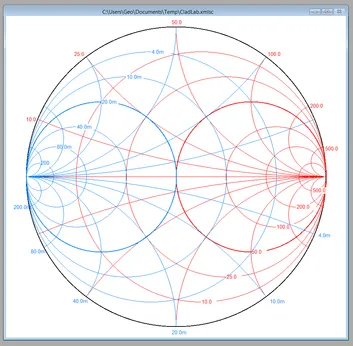
Smith charts are useful when designing impedance matching circuits between the antenna and RFID transceiver. A great free Smith chart program is Smith by Fritz Dellsperger.
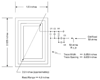
The following diagram is of a planar PCB 13.56MHz RFID antenna design, recommended by Texas Instruments (TI). TI states in Application Report SLOA135: Antenna Matching for the TRF7960 RFID Reader that,
“A rule of thumb is that the expected read range is twice the antenna diagonal measurement.”
Properties
Front-to-Back Ratio: The ratio (in dB) of the gain in the maximum direction vs. the gain of that 180° away from the maximum direction. Typical values for UHF antennas are around 20dB. It is a measure of the directionality of an antenna.
Linear Polarization (Dipole)
The best method if the tag orientation (with respect to the reader) is known and fixed.
Circular Polarization
The best method when the tag orientation could be anything. You lose at least 3dB of signal when using this method compared to linear polarization. A circular polarized antenna is not necessarily circular in shape, it’s to do with the fact the emitted electromagnetic wave’s electrical and magnetic components rotate 360° once every wavelength. You can get “left” or “right” polarized waveforms. Some antennas which are circularly polarized are:
- PCB slot antennas: Lengths between 20-50mm for UHF RFID is common on 1.6mm thick PCB
Standards
EPC Global Class 1 Generation 2 UHF Air Interface Protocol Standard “Gen 2”
One of (possibly the) most common standard for UHF RFID. Also called the EPC Global C1G2 standard. The international standard organization made it an amendment of the ISO18000-6C standard in 2006. A quote from the standards website:
“Commonly known as the “Gen 2” standard, this standard defines the physical and logical requirements for a passive-backscatter, Interrogator-talks-first (ITF), radio-frequency identification (RFID) system operating in the 860 MHz - 960 MHz frequency range. The system comprises Interrogators (also known as Readers), and Tags (also known as Labels).”
ISO/IEC 11784/11785
Standards for RFID tags on animals.
ISO/IEC 14443
Standard for RFID ID cards operating at 13.56MHz.
ISO/IEC 15693
A standard for HF RFID. Also called I-Code 2, I-Code STL, or C370. It defines the frequency (13.56MHz) and the communication methods (but not the data itself, this is vendor specific).
ISO/IEC 18000-3
Part 3 of the ISO/IEC 18000 standard. It is a standard for passive RFID item identification operating at 13.56MHz. This standard contains “3 non-contending nodes”,which are:
- Mode 1: Based on ISO/IEC 15693
- Mode 2: High-speed interface
- Mode 3: High-speed interface with 2 options. Option 1 is ASK based, option 2 is JSK based. Both use the same command interface as 18000-6C to be compatible with EPCglobal.
Is is specially designed for high-performance tag reading when the tag antennas are small and closely packed. They can employ phase-jitter modulation (PJM) to read closely packed tags.
ISO/IEC 18000-6C
Part 6 of the ISO/IEC 18000 standard. Defines parameters for RFID operating between 860-960MHz (UHF RFID). The EPC Global Class 1 Generation 2 UHF Air Interface Protocol Standard “Gen 2” standard was amended to this standard in 2006.
Recycling
Aside from recycling the RFID tag itself, RFID tags also affect the the recycling of the product it is attached too. The presence of paper, aluminum, copper, gold and silver in the RFID tag can introduce new challenges to the recycling of the product. The cost of an RFID tag is low and still dropping, reducing the incentive to recycle it. Active tags, mainly because of the battery, are considered electronic equipment under the European WEEE directive, and has to be recycled under the appropriate regulations. Passive tags are outside the WEEE scope. There are special glues/adhesives which facilitate the removal of the RFID tag from the product it is attached to. A current area of research (as of 2013) are biodegradable tags that degrade naturally on paper products.
RFID Software
Most RFID reader development kits come with supporting software to get a RFID project started quickly. They usually provide a PC-based GUI which connects to the reader via Ethernet, USB, or serial, can provides a readout of tags that are in range (and shows you things like their ID and RSSI), and allows you to adjust things like read interval and read power.
RFdump
Website: http://www.rf-dump.org/ In their own words:
RFDump is a backend GPL tool to directly interoperate with any RFID ISO-Reader to make the contents stored on RFID tags accessible.
It is a computer program, that when connected with standard RFID hardware, can read and write to a number of RFID tags. It has a strong “hacker” feel to it.
Manufacturers/Suppliers
You can use www.veryfields.net to do a parametric search for RFID tags. They require you to register to do search with all of the parameters, but registration is free.
VeryFields is the world’s largest showcase of RFID tags and provide RFID professionals with the best search tool for finding the best RFID tags for their needs.
LF
Priority 1 Design make LF reader modules.
HF
Skyetek make HF and UHF reader modules.
UHF
Impinj is a leading UHF RFID designer/manufacturer. They make the Monza family of RFID tag chips.
Alien is another leading UHF RFID manufacturer. They make the Alien Higgs-H2, -H3, -H4 range of chips as well as a varied range of inlays.
NXP manufacture the HiTAG (LF), ICODE (HF), and UCODE (UHF) range of RFID tags. These feature GPIO for simple open/closed circuit detection and also data communication with other chips.
Tageos is a manufacturer of UHF RFID inlays, using Alien or Impinj chips.
Skyetek make HF and UHF reader modules.
Unique Micro Design is a oceania region supplier of RFID products, based in Australia.
Printers
Zebra make RFID label printers.
External Links
SkyRFID is a useful site which explains how RFID works.


