Pulse Width Modulation (PWM)

Pulse width modulation (PWM) is a form of digital signal modulation in where the duty cycle of a square wave is varied (modulated) by another signal. It is commonly used to control things such as the brightness of LEDs, the speeds of motors, and the output voltage of switch-mode power supplies.
Almost all microcontrollers will have at least one PWM peripheral, which is a hardware block that generates a PWM signal under control of the CPU and firmware.
Frequency and Duty Cycle
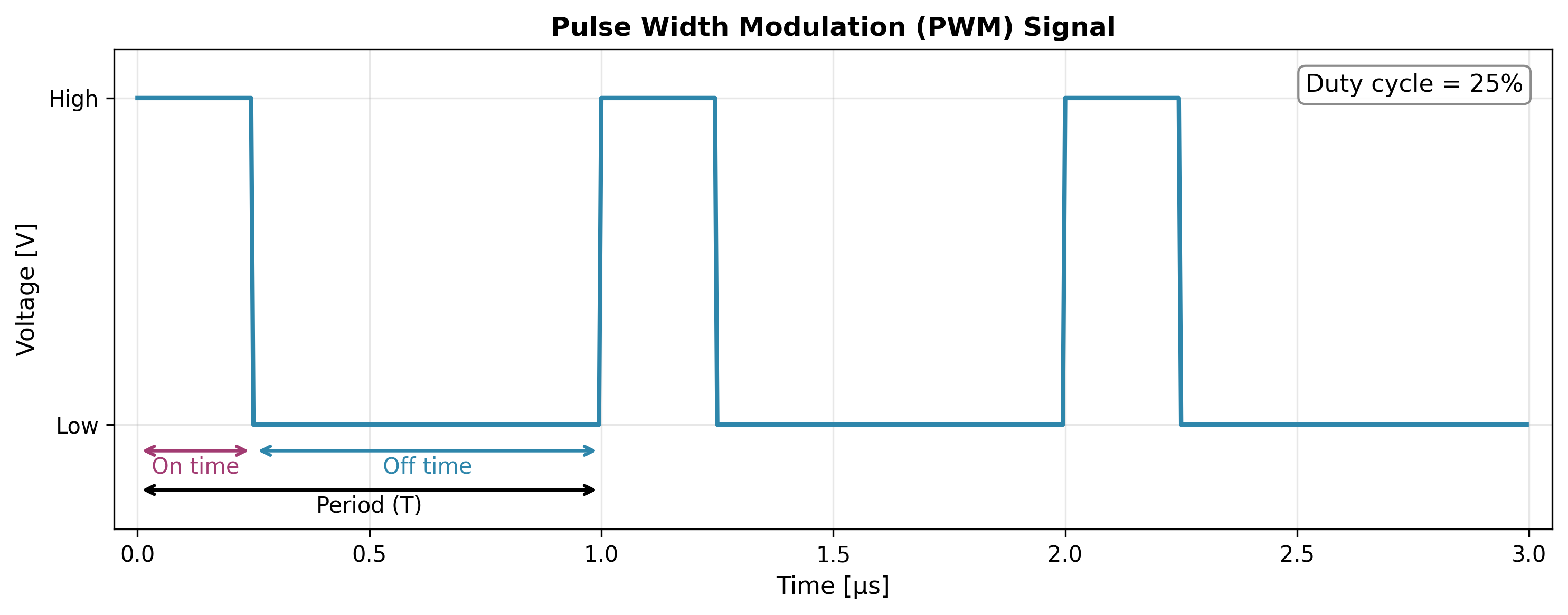
The frequency of the PWM signal is the number of complete cycles per second. This is normally controlled by a register in the PWM peripheral. You write to the register and this sets the number of PWM clock cycles per period (when the clock counter reaches the value, the counter resets back to 0).
The duty cycle is the percentage of the time the signal is on (active) compared to the total period of the signal. Again, it is usually controlled by a register. The peripheral compares the clock counter value with this value, and when they are equal the output is toggled. The output is reset back to the default state at the start of the next period, beginning the cycle again.
Operating Modes
PWM hardware peripherals may not support every one these modes.
Edge-Aligned (aka Asymmetric)
Edge-aligned, the most common (and usually the default) operating mode for a PWM peripheral, is when one edge of the switching from on/off is aligned with the edge of of the PWM period. In it’s most basic form it is simple to implement, requiring a counter, and two registers, one for resetting the counter (which determines the PWM period), and another for comparing with the count value, and switching the output if it’s greater than/less than/some logical expression (this sets the duty cycle).
Centre-Aligned (aka Symmetric)
Centre-aligned PWM is good for motor control as it generates fewer harmonics in the output voltage and current than asymmetric PWM. Some centre-aligned PWM hardware peripherals implement this by using a counter which changes direction every cycle. It counts up for the first cycle, down for the second, and then repeats. Doing this effectively reduces the PWM frequency by 2. So to arrive back at the same PWM frequency as when in asymmetric mode, you have to half the period (in terms of clock cycles). This reduces your duty cycle resolution.
Complementary Outputs
Some PWM peripherals have a complementary output feature. This is one PWM timer in hardware controls two output pins. One pin is the normal PWM signal, the other is the inverse of this. Complementary outputs are useful for driving H-bridges and other motor control circuits. Usually these peripherals will also support an adjustable programmable dead-time to prevent shoot-through.
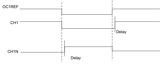
One example is the STM32 advanced motor control timers which are present in many of the STM32 MCU families including the STM32G series.1
Dithering
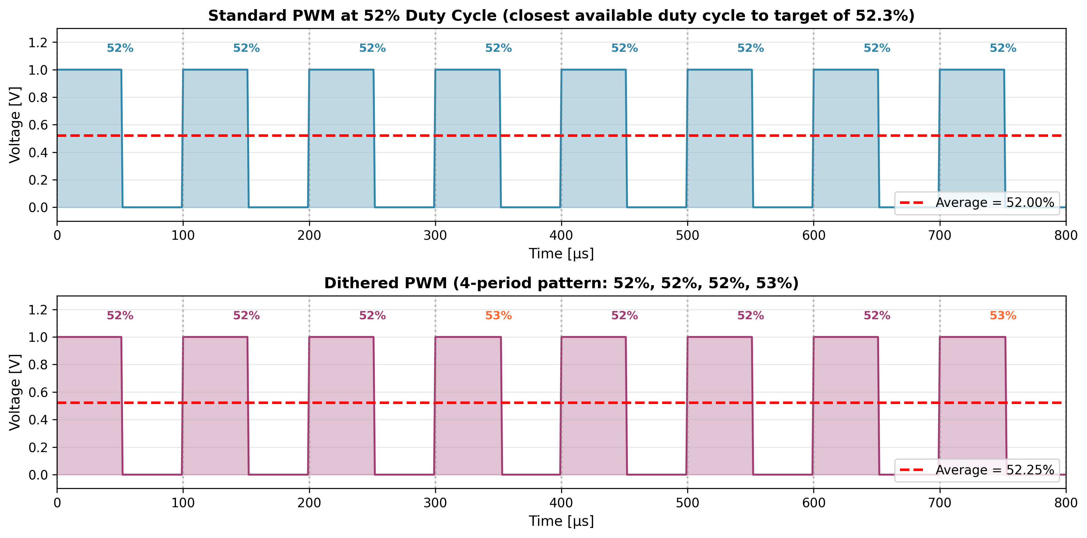
Some PWM peripherals support dithering to artificially increase the resolution of the PWM. This is where you vary the duty cycle between two adjacent discreet duty cycle values to give the appearance of a higher resolution PWM. The output PWM is then the average of the two duty cycle values. You do not need to strictly alternate between the two values (which would only give you an equivalent of twice the resolution) — instead you can spend more PWM cycles at one duty cycle than the other (e.g. 3 duty cycles at 52%, and then 1 duty cycle at 53% would give you can equivalent duty cycle of 52.25%).
This is a placeholder for the reference: fig-pwm-dithering-comparison shows how you could use 4 value dithering to achieve a better accuracy to the desired duty cycle of 52.3%. The top figure shows a standard PWM signal which only has 100 different duty cycle values, and so the closest it can get to 52.3% is 52%. The bottom figure shows a dithered PWM signal which can achieve an average duty cycle of 52.25%.
Most PWM peripherals support this by providing a way to pass a sequence of duty cycles values in which the peripheral will automatically iterate through. They usually have the option of automatically repeating the sequence, or firing an interrupt so that CPU can load the next sequence.
A sequence of 2^n values will give you additional resolution of n bits. For example, a sequence of 16 dithered values with give you 4 bits of additional resolution.
Creating a Dithering Sequence
To create a dithering sequence, you need to determine how many periods should be at each of the two adjacent duty cycle values. Here’s the algorithm:
-
Identify the two adjacent duty cycle counts: If you want a duty cycle of 23.6% and you have 160 clock cycles per PWM period (e.g. a 16 MHz clock feeding a PWM running at 100kHz), then you have a base resolution of .
The target duty cycle (in clock cycles) is then .
The lower duty cycle value (in clock cycles) is just the floor of this: .
The upper duty cycle value (in clock cycles) is then .
-
Calculate the number of upper and lower values in your sequence: You need periods at the upper value (38 clock cycles) and periods at the lower value (37 clock cycles), where is the sequence length.
You can calculate using the following equation:
So for our example with a sequence length of , we have:
This means we need 12 periods at 38 clock cycles and 4 periods at 37 clock cycles.
-
Create the sequence: We now need to create the sequence of duty cycle values. Rather than grouping all the upper values together, we need to distribute them evenly throughout the sequence for the best performance. This is achieved by using a Bresenham’s Line style algorithm.
The algorithm is as follows:
- Start with a counter set to half the sequence length.
- For each value in the sequence, decrement the counter by the number of upper values.
- If the counter is less than 0, append an upper value to the sequence and increment the counter by the sequence length.
- Otherwise, append a lower value to the sequence.
- Repeat until the sequence is complete.
So for our example, we start with a counter set to half the sequence length: .
Iteration 1: Decrement the counter: . Since , append upper value (38). Increment counter: . Sequence:
[38]Iteration 2: Decrement the counter: . Since , append lower value (37). Sequence:
[38, 37]Iteration 3: Decrement the counter: . Since , append upper value (38). Increment counter: . Sequence:
[38, 37, 38]Iteration 4: Decrement the counter: . Since , append upper value (38). Increment counter: . Sequence:
[38, 37, 38, 38]Continuing this pattern for all 16 iterations gives us the final sequence:
[38, 37, 38, 38, 38, 37, 38, 38, 38, 37, 38, 38, 38, 37, 38, 38]This sequence has 12 upper values (38) and 4 lower values (37), evenly distributed throughout.
-
Done!
Below is Python code that generates an arbitrary dithering sequence.
from typing import List, Tupleimport numpy as np
def generate_dithering_sequence(    target_duty_cycle: float,    base_resolution: float,    sequence_length: int) -> Tuple[List[float], float]:    """    Generate a dithering sequence to achieve a target duty cycle.
    Args:        target_duty_cycle: Desired duty cycle as a fraction (e.g., 0.236 for 23.6%)        base_resolution: Base PWM resolution (e.g., 1/160 = 0.00625 for 160 clock cycles per period)        sequence_length: Length of dithering sequence (e.g., 16)
    Returns:        sequence: List of duty cycle values (as fractions)        achieved_average: Actual average duty cycle achieved (as a fraction).    """    # Find the two adjacent duty cycle values    lower_value = np.floor(target_duty_cycle / base_resolution) * base_resolution    upper_value = lower_value + base_resolution
    # Calculate how many of each value we need    num_upper = round((target_duty_cycle - lower_value) * sequence_length / base_resolution)    num_lower = sequence_length - num_upper
    # Create sequence with evenly distributed upper values    sequence = []    error = sequence_length / 2  # Bresenham-like algorithm for even distribution
    for i in range(sequence_length):        error -= num_upper        if error < 0:            sequence.append(upper_value)            error += sequence_length        else:            sequence.append(lower_value)
    achieved_average = float(np.mean(sequence))    return sequence, achieved_average
# Example: 16 MHz clock, 100 kHz PWM, target 23.6% duty cycleclock_freq = 16e6  # 16 MHzpwm_freq = 100e3   # 100 kHzclocks_per_period = int(clock_freq / pwm_freq)  # 160 clock cyclesbase_resolution = 1.0 / clocks_per_period  # 1/160 = 0.00625
target_duty_cycle = 0.236  # 23.6%target_clock_cycles = target_duty_cycle * clocks_per_period  # 37.76 clock cycles
sequence, achieved = generate_dithering_sequence(target_duty_cycle, base_resolution, 16)sequence_clock_cycles = [int(x * clocks_per_period) for x in sequence]achieved_clock_cycles = achieved * clocks_per_period
print(f"Target: {target_duty_cycle:.1%} = {target_clock_cycles:.2f} clock cycles")print(f"Sequence (clock cycles): {sequence_clock_cycles}")print(f"Achieved: {achieved:.4%} = {achieved_clock_cycles:.2f} clock cycles")# Output: Target: 23.6% = 37.76 clock cycles#         Sequence (clock cycles): [38, 37, 38, 38, 38, 37, 38, 38, 38, 37, 38, 38, 38, 37, 38, 38]#         Achieved: 23.5938% = 37.75 clock cycles
You should be able to port this code to a microcontroller programming language of your choice (C, C++, Rust, e.t.c). I have made no attempt to make it as efficient as possible, and so for high performance applications you may need to optimise it (there is likely more optimum ways to calculate the dithering sequence).
Creating a DAC From a PWM Signal
You can create rudimentary digital-to-analogue converters (DACs) using a PWM peripheral and a low-pass analogue filter (e.g. a low-pass RC filter). This is because the low-pass filter will produce the average voltage of the PWM signal (provided the cut-off frequency is much lower than the PWM frequency), and you can use the duty cycle to directly control the average voltage linearly from 0V to the supply voltage.
This can be a useful trick when you are running short on true DAC peripherals on your microcontroller. You can also use a PWM peripheral to directly communicate an analogue value to a signal analyzer or oscilloscope. I have configured a PWM peripheral to output a duty cycle which was always 10x a measured voltage. For example, if the measured voltage was 1.23V, the PWM duty cycle would be set to 12.3%. I then connected this PWM output to a Saleae logic analyzer which was able to give me instant duty cycle readout at any point in the waveform (therefore instantly telling me the voltage without any complex mental maths). This is a great alternative to debug logs over a serial port for high speed measurements.
A Warning About PWM And Oscilloscopes
When viewing a PWM output on an oscilloscope, you can experience what is called aliasing, and oscilloscope seems to show that the PWM signal is stopping and then restarting at a rate much slower than the PWM frequency.
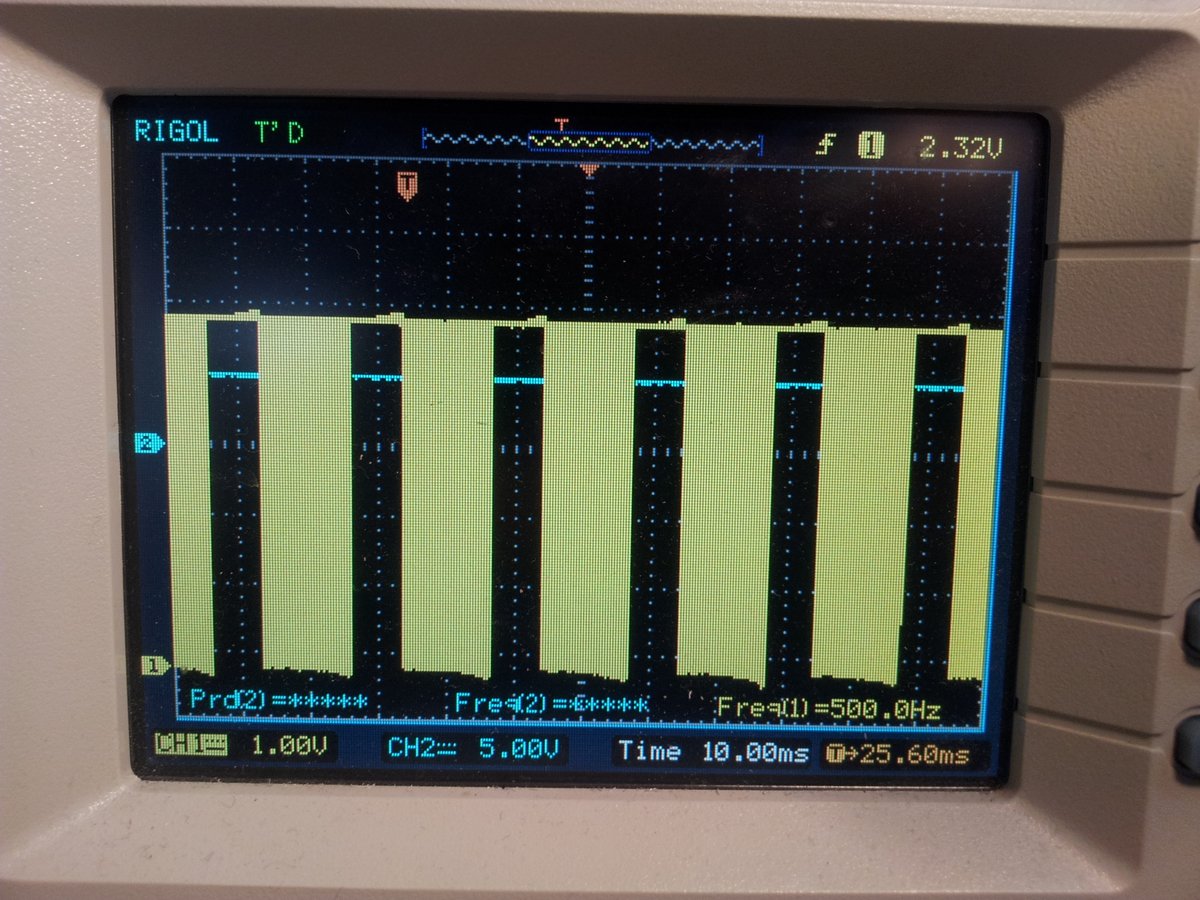
While your PWM could actually be doing this, more often than not what you are seeing is an artefact caused by the digital sampling of the oscilloscope. The following picture shows a 15kHz PWM signal appearing to stop and start every 10ms or so. I can assure you that the PWM signal is fine, it is the Rigol 100MHz oscilloscope showing the wrong thing.
Footnotes
-
STMicroelectronics. AN4013 - Application note - Introduction to timers for STM32 MCUs. Retrieved 2024-07-11, from https://www.st.com/resource/en/application_note/an4013-introduction-to-timers-for-stm32-mcus-stmicroelectronics.pdf. ↩