Kirchhoff's Circuit Laws
Kirchhoff’s circuit laws are two laws that describe how currents and voltages sum up in electrical circuits. Along with Ohm’s law, they are probably the most often used laws in circuit design. They are relatively easy to understand and quickly become second nature.
Kirchhoff’s current law (KCL) describes how the currents entering and leaving a node sum up to zero. Kirchhoff’s voltage law (KVL) describes how the voltages around a closed loop sum up to zero. More on these below!
Kirchhoff’s Current Law
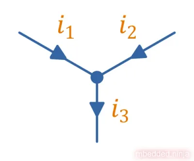
Kirchhoff’s current law (KCL) states that the sum of currents entering an electrical node must equal the sum of currents leaving that node1.
For example, given the circuit in This is a placeholder for the reference: fig-kirchhoffs-current-law-i1-i2-i3, Kirchhoff’s current law says that the following must be true:

The dot represents an electrical node, which is essentially a connection point between two or more conductive parts of the circuit. KCL is a consequence of the conservation of charge2.
Rather than stating that the currents entering and leaving a node must sum up to zero, we can assign a sign to currents. If currents entering the node are positive, then currents leaving the node are negative, then we can simply write the law as2:
It might be surprising that KCL works for capacitors, even though we think of capacitors storing charge. The reason KCL holds is that just as much charge leaves the negative plate of the capacitor as enters the positive plate, such that the net change in charge is zero.
Kirchhoff’s Voltage Law
Kirchhoff’s voltage law (KVL) states that the sum of voltages around a closed loop must equal zero. This can be written as2:
where:
is the index of the element in the loop,
is the voltage across the th element in the loop.
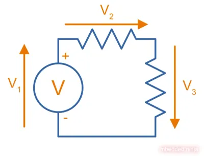
Lets look at the circuit shown in This is a placeholder for the reference: fig-kirchhoffs-voltage-law-diagram:
Kirchhoff’s voltage law says that the sum of the voltages around the loop must equal zero, so we have:
We are walking clockwise around the loop, and orange arrows have been added to show the direction. Think of using a volt meter and placing the red (positive) probe at the tip of the arrow and the black (negative) probe at the tail of the arrow. The voltage across the voltage source will be positive, and the voltage across the two resistors will be negative.
Footnotes
-
Khan Academy. Course: AP/College Physics 2 > Unit 3 > Lesson 1: Current, resistivity, and Ohm’s law > Kirchhoff’s laws. Retrieved 2024-10-22, from https://www.khanacademy.org/science/ap-physics-2/x0e2f5a2c:ap-2-circuits/x0e2f5a2c:ap-2-circuits-with-resistors/a/ee-kirchhoffs-laws. ↩
-
Wikipedia (2024, May 20). Kirchhoff’s circuit laws. Retrieved 2024-10-22, from https://en.wikipedia.org/wiki/Kirchhoff%27s_circuit_laws. ↩ ↩2 ↩3
-
Wikipedia (2024, Oct 2). Electric current. Retrieved 2024-10-22, from https://en.wikipedia.org/wiki/Electric_current. ↩


