Board Bring-Up

Board bring-up is the process of powering up and testing a newly designed PCB to make sure it is working correctly. It is typically done by the designers of the PCB once the first prototypes have been manufactured.
There is a skill to performing board bring-up correctly. This page aims to cover some of the key tips and tricks to doing the job well!
Add Zero Ohm Links to PSUs
If you add zero ohm links in series with the outputs of on board PSUs, this allows you disconnect any downstream circuitry when powering them up and testing them for the first time. This prevents you from destroying downstream circuitry if the voltage goes higher than expected (e.g. incorrect feedback resistor values, open circuit feedback resistors, instability issues, etc).
This also allows you to load test the PSU with a programmable load (or other means, light bulbs and power resistors are common) across it’s full operational range.
Using Low Voltage DC To Test AC Mains
A neat trick you can use sometimes is to use 100-120 VDC to test AC mains powered devices. This works for powering devices which have a power module to convert the AC to low voltage DC. Typically these power modules are rated for 90-240 VAC input, but due to the full-bridge on the input and loose loose tolerances on the input voltage, they can work ok from 100-120 VDC also.
This reduces the risk of electrocuting yourself when bringing up a new board. Be careful as 120 VDC will still give you a shock, but it much less dangerous than 230 VAC (which peaks at ). 120V is right on the limit on what a lot of countries regulations consider “extra low voltage” (ELV).
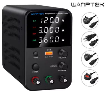
You can purchase cheap bench-top PSUs that can output 120 VDC (120 VDC happens to be the upper limit of common bench-top PSUs).
Thermal Cameras
Thermal cameras are a great tool to identify hot spots on a board after it has been powered up. In the case of a design or soldering fault, they can serve as an early warning system so you can kill the power before any components overheat and get damaged.
A “beating” throb on the thermal camera (a spot that is cycling between hot and cold every few seconds) is a common sign that a component is reaching it’s thermal limit, switching off and then waiting to cool down before switching back on (they typically have some hysteresis). I’ve seen this happen to linear regulators that had a short on their output.
Footnotes
-
Wanptek. 120V DC PSU [product]. AliExpress. Retrieved 2025-10-22, from https://www.aliexpress.com/item/1005007714067372.html. ↩