PCB-Related API

Creating Objects
Tracks
The following code shows how to create a track (a straight line, curved ones are called arcs) on a PCB.
procedure CreateTrack();var    board : IPCB_Board;    track1 : IPCB_Track;begin    // Obtains the PCB server and the PCB document    board := PCBServer.GetCurrentPCBBoard;    if (board = nil) then exit;
    track1 := PCBServer.PCBObjectFactory(eTrackObject, eNoDimension, eCreate_Default);    track1.x1 := MMsToCoord(xm + innerRadiusMm*sin(currentAngle));    track1.y1 := MMsToCoord(ym + innerRadiusMm*cos(currentAngle));    track1.x2 := MMsToCoord(xm + (innerRadiusMm + nMinus1PadBaseHeightMm)*sin(currentAngle));    track1.y2 := MMsToCoord(ym + (innerRadiusMm + nMinus1PadBaseHeightMm)*cos(currentAngle));    track1.Width := MMsToCoord(trackThicknessMM);
    Board.AddPCBObject(track1);end;
Arcs
The following code shows how to create an arc (a curved line) on a PCB.
arcN_2 := PCBServer.PCBObjectFactory(eArcObject, eNoDimension, eCreate_Default);arcN_2.XCenter := MMsToCoord(xm);arcN_2.YCenter := MMsToCoord(ym);arcN_2.Radius := MMsToCoord(outerRadiusMm - nPadBaseHeightMm);arcN_2.LineWidth := MMsToCoord(0.254);arcN_2.StartAngle := 90 - (nTowerStartAngle*180)/(Pi) - (currentAngle*180)/Pi;arcN_2.EndAngle := 90 - (currentAngle*180)/Pi;arcN_2.Layer := eTopLayer;arcN_2.LineWidth := MMsToCoord(trackThicknessMM);
Board.AddPCBObject(arcN_2);
User Input
The following functions belonging to the IPCB_Board object request input from the user:
GetObjectAtCursorGetObjectAtXYAskUserIfAmbiguousChooseRectangleByCornersChooseLocationGet The User To Select A Position
The following code prompt the user to select a position on the PCB. The position (as x and y co-ordinates) the user clicks can then be used in proceeding code.
// Request for the user to select the centre of the objectif (board.ChooseLocation(xm,ym,'Choose the centre of the circular pads.') = true) thenbeginend;Get The User To Select Objects
To prompt the user to select objects, use the function GetObjectAtCursor(); on a PCB board (IPCB_Board) object. It’s syntax is:
IPCB_Primative GetObjectAtCursor( TObjectSet objectSet, TLayerSet layerSet, TPCBString statusBarText);where objectSet is a list of all object types that the user can select (think of it as a mask), layerSet is a list of all layers that objects can be selected on (yet again, a mask), and statusBarText is the text you want to display in the status bar while the user selects the objects.
The TObjectSet variable is normally made by calling the function MkSet(), which makes a set from the passed in object(s) (this only required when scripting in Delphi, as Delphi doesn’t natively support sets). The objects you can pass into MkSet() are part of the TObjectID enumeration and include:
eNoObjecteArcObjectePadObjecteViaObjecteTrackObjecteTextObjecteFillObjecteConnectionObjecteNetObjecteComponentObjectePolyObjecteRegionObjecteComponentBodyObjecteDimensionObjecteCoordinateObjecteClassObjecteRuleObjecteFromToObjecteDifferentialPairObjecteViolationObjecteEmbeddedObjecteEmbeddedBoardObjecteTraceObjecteSpareViaObjecteBoardObjecteBoardOutlineObjectThe example below requests the user to select a component from an layer.
Procedure GetComponent;var    board       : IPCB_Board;    comp      : IPCB_Component;begin
    board := PCBServer.GetCurrentPCBBoard;    if board = nil then exit;
    // Get component    comp := Board.GetObjectAtCursor(        MkSet(eComponentObject),        AllLayers,        'Choose Source Orientational Component');        if Source = nil then exit;end;
Check That A PCB Board Is Selected
You commonly need to check that when a script is run, the active window is the right thing for the script to act on. The following code shows how to check if a PCB board file is loaded (.Pcb), and it feature at the start of lots of the other code examples. If a PCB board is not currently selected, the script quietly exits.
// obtains the PCB server and the PCB documentboard := PCBServer.GetCurrentPCBBoard;if (board = nil) then exit;Creating PCB Regions (The Contour Method)
You can create PCB regions (which are similar to polygons, but have slightly different properties/behaviors) using contours.
Define The Objects
Define the following objects after the var keyword and before the begin keyword.
board : IPCB_Board;contour : IPCB_Contour;region : IPCB_Region;To Generate An Arc Section Of A Region
Use the following function to create an arc an add it to the contour (which will be used once all the segments have been added to generate the region).
PCBServer.PCBContourMaker.AddArcToContour( contour contour1, double startAngle, double stopAngle, TCoord xCenter, TCoord yCenter, Boolean Aclockwise);Make Aclockwise be true if going clockwise, false if going clockwise.
The Generate A Straight Section Of A Region
Use the following function to create a line segment and add it to a contour (which will be used once all the segments have been added to generate the region). Note that it is slightly simpler to add a line segment to a contour than an arc, basically because for a line all you have to do is define the start and end points.
contour.AddPoint(x : interger, y : integer);How To Finally Add The Region To The PCB
Once you have defined a region by using the contour object, you can add it to the PCB with the following code. This assumes
region := PCBServer.PCBObjectFactory(eRegionObject, eNoDimension, eCreate_Default);region.SetOutlineContour(contour);region.Layer := eTopLayer;Board.AddPCBObject(region);Creating PCB Polygons (The PolySegment Method)
You can create polygons on a PCB by using the IPCB_Polygon and TPolySegment classes.
Here is an example that will create a rather large, square polygon on the top layer of your PCB.
procedure CreatePolygonUsingPolySegments();    var        polygon : IPCB_Polygon;        polygonSegment1 : TPolySegment;        polygonSegment2 : TPolySegment;        polygonSegment3 : TPolySegment;        polygonSegment4 : TPolySegment;        Board;    begin        // Start of undo unit        PCBServer.PreProcess;
        // Define the polygon segments        polygonSegment1 := TPolySegment;        polygonSegment1.Kind := ePolySegmentLine;        polygonSegment1.vx := MMsToCoord(500);        polygonSegment1.vy := MMsToCoord(500);
        polygonSegment2 := TPolySegment;        polygonSegment2.Kind := ePolySegmentLine;        polygonSegment2.vx := MMsToCoord(500);        polygonSegment2.vy := MMsToCoord(1000);
        polygonSegment3 := TPolySegment;        polygonSegment3.Kind := ePolySegmentLine;        polygonSegment3.vy := MMsToCoord(1000);
        polygonSegment4 := TPolySegment;        polygonSegment4.Kind := ePolySegmentLine;        polygonSegment4.vy := MMsToCoord(500);
        // Build the polygon        polygon := PCBServer.PCBObjectFactory(ePolyObject, eNoDimension, eCreate_Default);        // This next one is really important        polygon.SetState_PointCount(4);        polygon.SetState_Segments(0,polygonSegment1);        polygon.SetState_Segments(1,polygonSegment2);        polygon.SetState_Segments(2,polygonSegment3);        polygon.SetState_Segments(3,polygonSegment4);        polygon.SetState_Segments(4,polygonSegment1);        polygon.SetState_PolygonType(eSignalLayerPolygon);        polygon.SetState_PourOver(true);        polygon.SetState_PolyHatchStyle(ePolySolid);        polygon.SetState_BorderWidth(false);        polygon.SetState_Layer(eTopLayer);        polygon.SetState_RemoveNarrowNecks(false);
        // Add polygon to PCB        Board := PCBServer.GetCurrentPCBBoard;        Board.AddPCBObject(polygon);
        // This must be done after adding the polygon to the PCB        polygon.Rebuild;
        // End of undo unit        PCBServer.PostProcess;
        // Refresh PCB        Client.SendMessage('PCB:Zoom', 'Action=Redraw' , 255, Client.CurrentView);end;
To Update The PCB Window
Use the Client object to update the PCB window. This will update the PCB to show any changes that have been made to it by preceding code (it is not updated automatically). It is useful to call this at the end of a script to update the PCB and show the user the changes that have been made. If you don’t call this, the the user will only see the changes once this method is called by another process.
Call Client.SendMessage("PCB:Zoom", "Action=Redraw" , 255, Client.CurrentView)Undo
With specifically calling the functions PCBServer.PreProcess and PCBServer.PostProcess, you will lose undo/redo functionality when/after running altium scripts.
Make sure that you call PCBServer.PreProcess and PCBServer.PostProcess after doing any action that would change the PCB in anyway. If you are losing Undo functionality, it is likely due to the fact you are calling PreProcess without calling PostProcess. Essentially, any action done on the PCB between these two function calls is counted as one ‘Undo’. The code below shows how to use these two functions correctly.
Sub UsingUndoProperly()
PCBServer.PreProcess ' Put script code that changes the PCB here ' All of this will be one 'Undo' PCBServer.PostProcess
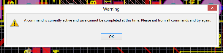
PCBServer.PreProcess ' All PCB changes done here will be another 'Undo' operation PCBServer.PostProcessEnd SubYou can get the following error when trying to save if you haven’t called PCBServer.PostProcess and equal number of times as PCBServer.PostProcess. So far, if this does occur, I haven’t worked out how to save the document (all changes since last save are lost!).
Updating Component Links
You can open the “Edit Component Links” window by running the following commands (VBscript):
ResetParametersCall AddStringParameter("ObjectKind", "Project")Call AddStringParameter("Action", "ComponentLinking")Call RunProcess("WorkspaceManager:DocumentOptions")Note that this does not update the component links automatically, but just opens the “Edit Component Links” window.
Zoom
You can change the zoom on a PCB by using the following commands (VBscipt):
ResetParametersCall AddStringParameter("ZoomLevel", "2.0")Call RunProcess("PCB:Zoom")PCB Layer Info
You can get the currently selected PCB layer with the code:
Board.CurrentLayerOn a valid IPCB_Board object.
You can use the LayerToString() and StringToLayer() functions to convert a PCB layer object into a human readable string and back again. For example, if the PCB was currently on the top copper layer, you could do the following:
ShowMessage(LayerToString(Board.CurrentLayer))
' This will display the current layer to the user, if say, the top' copper layer was currently selected, it would display "Top Layer".
PCB Components
PCB Components have a child object called Name, which refers the the designator.
The Name Object
The confusing thing is, while the parameter Width refers to its width, the parameter Size refers to the designator height.