ARM Cortex-M3
| Date Published: | |
| Last Modified: |
Child Pages
Overview
The ARM Cortex-M3 is a computer CPU architecture introduced in 2004 and designed for microcontrollers. It uses the 32-bit Thumb-2 instruction set (which supports the 16-bit Thumb instructions). It does not support ARM instructions.
Processor Modes
The processor supports two modes of operation, thread mode and handler mode. Both privileged and user code can run in thread-mode, while only privileged code can run in handler mode.
Privileged Mode
When the CPU is running in privileged mode, the code can do anything it wants (think of a system administrator). The processor starts running in privileged mode when it comes out of reset.
User (Un-Privileged) Mode
User mode is a “safer” way of running code on the Cortex-M3. When the processor is running in user mode, the executed code can be restricted from using certain instructions and also access to certain registers (such as system control registers).
The only way to go from user mode back into privileged mode is through the firing of a handler (interrupt).
Stack Pointers
The Cortex-M3 has two stack pointers, the main stack pointer (MSP) and the process stack pointer (PSP). The MSP is used when handling interrupts and optionally during normal execution, while the PSP is only used during normal processor execution. In a RTOS environment, ARM recommends that the MSP is used for both interrupts and kernel execution, while the PSP is used for thread/task execution.
Memory
The memory on the Cortex-M3 has a single continuously mapped memory address space. The memory map is shown below.
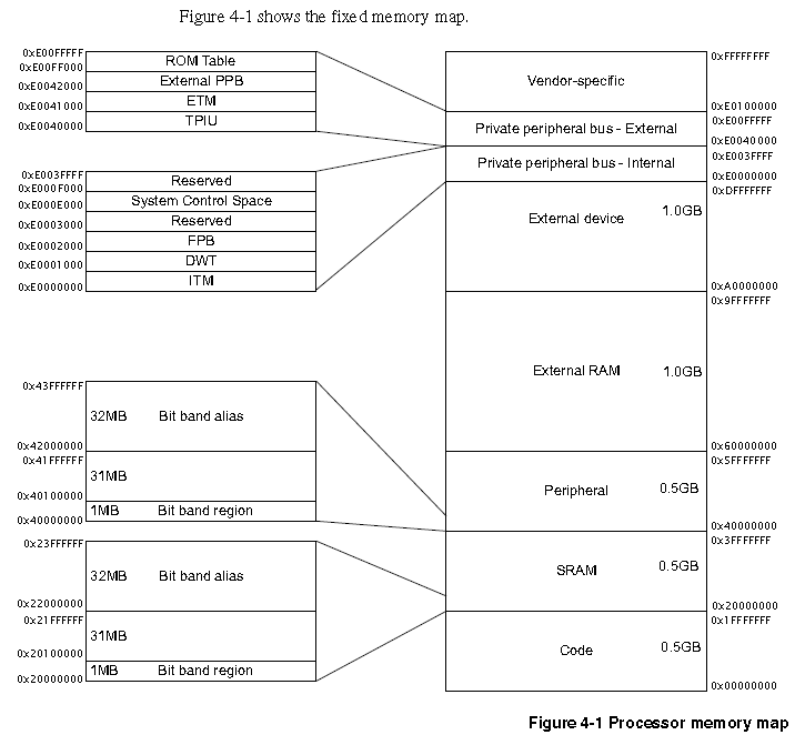
The ARM Cortex-M3 CPU fixed memory map. Image from http://infocenter.arm.com/help/topic/com.arm.doc.ddi0337e/DDI0337E_cortex_m3_r1p1_trm.pdf.
Data Types
The Cortex-M3 supports 3 data types:
- 32-bit Words
- 16-bit Half-words
- 8-bit Bytes
Note that you are not limited to only these data types in C! We are talking about the data types that the CPU natively supports, but with the appropriate assembly/C code, you can use many more.
The processor can access memory in either little-endian or big-endian format, however the code (usually stored in Flash) has to be stored as little-endian. The processor has a pin called BIGEND which allows you to select the endianess of the memory at reset. Note that is up to the vendor’s discretion to route this “pin” to an actual hardware pin on the microcontroller. More often than not you will not have access to this pin, as the memory on a microcontroller is usually incorporated into silicon chip itself, so the endianess is known at production.
Interrupts
The powerful interrupt controller on the Cortex-M3 is called the NVIC (nested vectored interrupt controller).
The Cortex-M3 supports up to maximum of 240 interrupts, although the exact number is vendor specific (and usually lower than this). The NVIC supports a variable number to priority bits (from 3 to 8, giving a range from 8 priorities to 256 priorities).
It supports both level and pulse triggered interrupts, dynamic re-prioritisation, priority grouping (see below), tail-chaining of interrupts, and automatic saving of the processor state on input and restoration on output, with no extra overhead).
Interrupt Control Register
Address: 0xE000ED04
You can use bits [8:0] from this register to check if an interrupt is currently active, as shown in the example code below.
| |
Interrupt Active Registers
The Cortex-M3 has a group of registers which can be read to find out which (if any) interrupt is active. These registers are called the “Active Bit” registers. The reason I say registers is that because there are 240 interrupts, multiple 32-bit registers are required. They start at memory address 0xE000E300 to 0xE000E31C. All of their values on reset are 0x00000000.
You can use these registers to find out in code if the processor is currently executing code from within an interrupt (although using the interrupt control register is easier).
Priority Grouping
The Cortex-M3 NVIC supports priority grouping of interrupts. This is controlled by the single bit field PRIGROUP in the Application Interrupt and Reset Control Register.
The grouping divides the 8-bit priority register for each interrupt into two sections, one part for the pre-emption field, and the other part for the subpriority field. the PRIGROUP register allows you to change the ratio of pre-emption bits to subpriority bits (e.g. 7:1, 5:3, 2:6). The pre-emption field can have no bits, but the subpriority field always has to have at least 1.
SysTick
The Cortex-M3 has a build in “systick” hardware peripheral. It is used in some ports of FreeRTOS for calling the FreeRTOS tick handler function (the heartbeat of the FreeRTOS).
CMSIS
CMSIS (Cortex-M Software Interface Standard) is a vendor-independent hardware abstraction layer for the entire Cortex-M processor series.
Supports core debug/trace facilities.
Microcontrollers Which Use This Architecture
- Atmel SAM3A
- Atmel SAM3N
- Atmel SAM3S
- Atmel SAM3U
- Atmel SAM3X
- Energy Micro EFM32
- Cypress PSoC 5
- Cypress PSoC 5LP
- NXP LPC1300
- NXP LPC1700 (used by mbed)
- NXP LPC1300
- PSoC 5
- PSoC 5 LP
- STM32
External Links
Check out the official marketing page for the Cortex-M3
Authors


This work is licensed under a Creative Commons Attribution 4.0 International License .