Electric Skateboard Updates
| Date Published: | |
| Last Modified: |
04/02/2012
Finished the battery mounts, drilled holes and mounted the electronics enclosure as well as the three light brackets.
02/02/2012
The second prototype h-bridge circuit blew up! It was working when powering a light, and also the 800W motor with no load. But as soon as I added a load to the motor (in the form of my body-weight and a skateboard), the h-bridge blew up. The top MOSFET broke and when into their infamous short mode, which then caused some of the prototype board tracks to blow up. Not sure of the cause, most likely noise spikes from the motor, but I had TVS diodes everywhere! I replaced the MOSFET, fixed the tracks, and it once again blew up, this time without a PWM signal being applied (which means it should of never turned on the MOSFET)!
25/01/2012
News is that the PCBs won’t be made by Massey anymore, so I’m going to have to submit them to a professional PCB manufacturer. Considering either Circuit Labs or PCB Zone (see more info on PCB manufacturers here).
07/01/2012
After going nuts on this project in the last week, I have nearly finished the PCB routing for the skateboard PCB, the first of two boards (the other is the remote PCB).
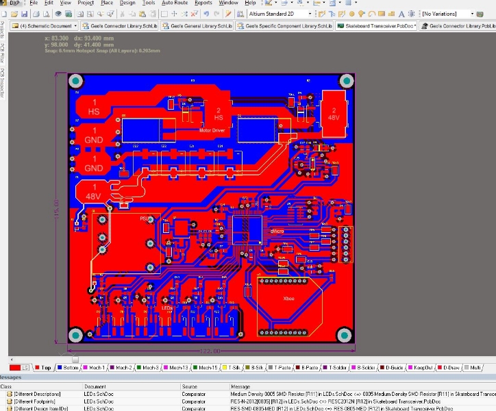
05/01/2012
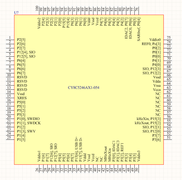
Finally got some time of work to ‘start’ finishing this thing! Worked on the schematics today, and are planning to get a PCB done so that Massey in Palmerston North can make some rough 2-layer PCB prototype boards for testing. I brought a PSoC development kit a while back in anticipation of using it to develop code/test hardware before these boards are ready.
14/03/2011
Got the motor and cog back from Niven’s! Awesome work. They shaved a D into the shaft and put a grub screw in the side to hold the cog in place.
12/03/2011
Fixed the Li-Po battery. Removed the dead cell and reconnected the remaining cells and terminals to make a 7 cell battery pack. It was quite hard to solder a bridge on the terminals, they are huge pieves of metal and solder which make good heatsinks, my soldering iron and mini blow torch had a hard time melting the solder.
11/03/2011
Nivens engineering is kindly cutting a ‘D’ into my motor shaft, so the cog can slide on, as well as drilling a hole for a grub screw to keep the cog in place (their idea, I was just going to rely on friction, but the experts siad thats bad!)
05/03/2011
Protoboard made! O.K., so it’s just the two trucks fixed to a piece of MDF. But it will come in handy for testing…
08/01/2011
Sourcing the axles, wheels and drive parts at the moment. Greenskate (a company on Trade Me sells parts for electric skateboards. I am looking into these at the moment. The XBee modules are playing up slightly. One of them seems to turn off some of the time, and the pin voltages drop to 2.1V (should be Vcc, which is 3.3V). After a while they reset and go back up to 3.3V. This problem seems to occur sporadically and go away in the same fashion. Weird. I hoping proper PCBs will solve this.
05/01/2011
State machine developed further. I have now connected a piezo buzzer up to the skateboard ATmega8 to indicate important events such as turning on and the battery getting flat. The piezo is also used to sound an alarm when the skateboard is moved without authorisation. I have connected a small tilt switch that triggers the alarm when the skateboard is moved from rest. The remote will be able to be used to arm the alarm. I may look at getting more tilt switches for more sensitivity to movement. The USART baud rate bug showed its head again today. It seems that each micro works when a different baud rate value is set in the register, and neither are what the ATMEL datasheet recommends for the lowest percentage error. Weird… I got an email back from green skate today about the technical specs of their rear axles. This could be a good option for the skateboard.
04/01/2011
State machine for the skateboard is working and is controllable by the remote! Currently, the remote can turn on and off the skateboard. The motor is disabled in the off state, and I hope to work some power saving features into this mode as well. Skateboard can also work out when the remote is in range. Also trying to implement a comms timeout function, that turns of the motor if no packet from the remote is received with a certain number of state machine cycles, but this is still buggy and not working properly.
27/12/2010
Bug found! USART data being sent at the wrong baud rate, even though everything was set correcty. At first I though the internal osciallator was drifting, but after replacing it with an external crystal and no progress, I changed the reg value that sets the baud rate (on the off chance). Lowering it from 51 (what ATMEL recommends for 0.2% error at 9600 baud, 8MHz crystal), down to 48. This made the usart data send and receive perfectly! Weird?!?. I must of spent 20+ hours debugging this…
26/12/2010
Been debugging the comms between the two chips today. Wrote code to write a package, and then decode the package on the other chip. Tested this with a direct link, and it works fine. The only problem is the XBee modules, data corruption is frequent when using them. I think it might be a frequency mismatch between the chip and the Xbee module. I am currently using the Atmega8 internal oscialltor set at 8Mhz without loading the calibration byte into OSCAL (this made it worse). It could be off by enough that the XBee module gets frame errors…
24/12/2010
Been working on the electronics quite extensively in the last few days. I have built the second prototype board so now there is a handhed receiver and skateboard circuit. The last few days have been primarly based around getting the ATmega8 USART working, building a TTL to RS232 serial level shifter, and then the XBee modules talking to each and the chip. Success has just been reached, but not without difficulty. I have been having voltage drop-out issues on the breadboard causing weird behaviour. Sometimes 400mV was dropped over a ’track’! This was fixed by making direct connections from the regulator to the power consuming devices, bypassing the high resistance breadboard connections. The XBee modules were playing up also, and after many hours of debugging I finally fixed them by swapping the two identical modules around. Wtf?!?
21/12/2010
Build a rpm counter using an infrared diode and transistor. I glued a piece of KNEX onto the rotor that spun around and blocked the infrared beam twice per revolution. I connected the oscilloscope up the the transistor section and could easily detect when the beam was blocked. Check out the electrical desgin page.
18/12/2010
Managed to get the micro-controller outputting 50Hz variable-duty cycle PWM. The duty cycle is varied with a potentiometer (will later be a trigger). Used this to give the motor a test spin. After almost wrapping my fingers up in the motor, success! The control is a bit dodgy and for some reason the control only works between about 5% and 25% duty cycle. I’m not sure if this is how it’s supposed to operate of if I’m doing something wrong, but I will investigate.
17/12/2010
Parts from Hobby King arrived in the mail! See the photo’s below…
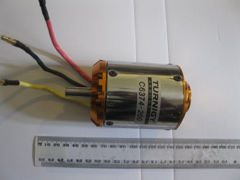
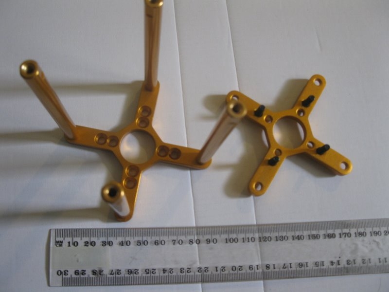
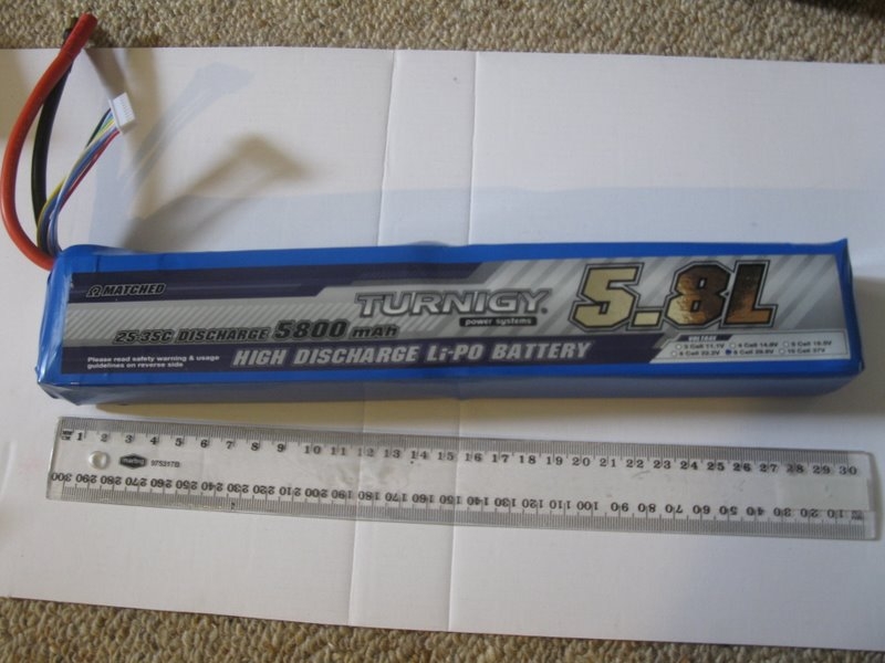
09/12/2010
BLDC motor, speed controller, Li-Po batteries, charger and other motor accessories ordered from www.hobbyking.com
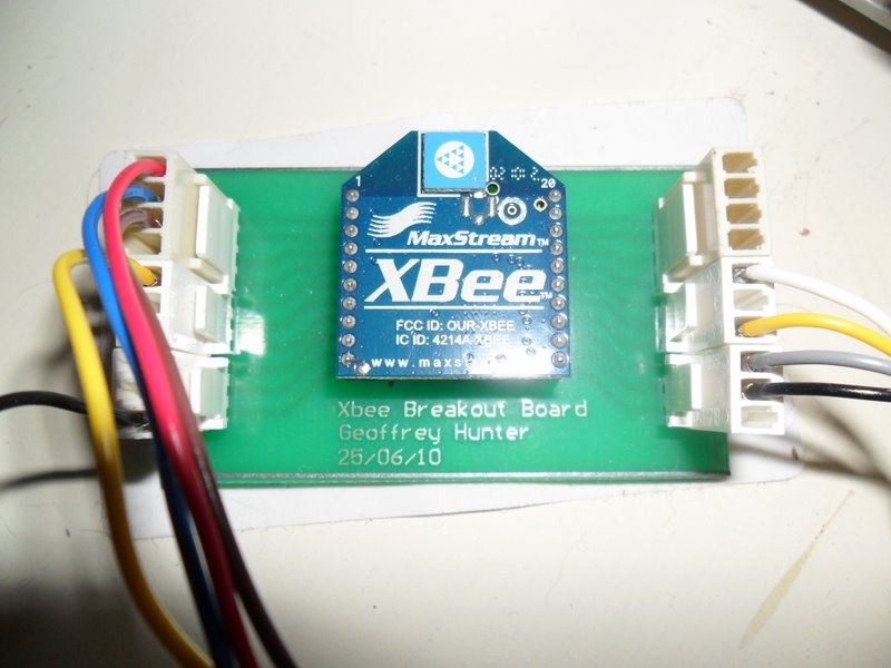
25/06/2010
Designed breakout boards for the Xbee modules. These will be used to test the module before making the final circuits.
12/05/2010
Purchased ATmega8 micro-controllers, Xbee modules, and various other components
20/04/2010
Brought skateboard of mate for NZ$20.
Authors


This work is licensed under a Creative Commons Attribution 4.0 International License .