Voltage-Level Translators
| Date Published: | |
| Last Modified: |
Overview
Voltage-level translators (and hence, voltage-level translation) refers to the conversion to digital logic signals from one voltage level (e.g. +3.3V) to another (e.g. +5.0V) (the different voltage levels are also called voltage domains). It is commonly used to provide communication capability between two ICs which are operating of a different voltage rail. Voltage-level translators are also called level shifters1.
Voltage-level translators can also be used to prevent backfeeding (whether or not the two sides of the circuitry are at different voltage levels).
Do not confuse voltage-level translation with voltage converters (e.g. linear regulators or SMPS) which are designed to provide power.
Topologies
There are many different ways of making a voltage-level translator. Some of the topologies are:
- Discrete MOSFETs: Inherently bi-directional, but place relative voltage level restrictions between side A and side B.
- Totem-poles: Require a
DIRpin or auto-direction to be bi-directional. No relative voltage level restrictions between side and side B. - Four-port MOSFETs with Gate Bias (e.g. the LSF0101): Inherently bi-directional, but place relative voltage level restrictions between side A and side B. Small amount of leakage current from the higher voltage rail to the lower voltage rail, lower voltage rail must be able to sink this current.
These topologies are discussed more in the sections below.
Discrete MOSFET Voltage-Level Translators
The below schematic shows a simple circuit for voltage-level translation using a single MOSFET and pull-up resistors. It supports bi-directional digital signal translation.
- Simple circuitry.
- Weak pull-up for certain edges in certain directions, resulting in slow transition speeds.
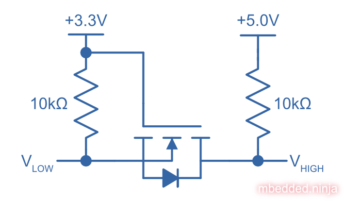
What happens if \(V_{low}\) is driven?
If \(V_{low}\) is driven high, then the gate-source voltage of the N-channel MOSFET (\(V_{GS}\)) is \(0V\), and the MOSFET is OFF. This means that \(V_{high}\) is pulled high by its \(10k\Omega\) resistor.
If \(V_{low}\) is driven low, then the gate-source voltage of the N-channel MOSFET (\(V_{GS}\)) is now \(+3.3V\), and the MOSFET is ON. This means that \(V_{high}\) is driven LOW through the MOSFET.
What happens if \(V_{high}\) is driven?
If \(V_{high}\) is driven high, the body-diode of the MOSFET will be reverse-biased, and OFF. This means that the source of the MOSFET will be pulled to \(+3.3V\) by the \(10k\Omega\) resistor, (\(V_{GS}\)) will be \(0V\), the MOSFET OFF, and \(V_{low}\) also high because of it’s \(10k\Omega\) resistor.
If \(V_{high}\) is driven low, the body-diode of the MOSFET will be forward-biased, and switch ON. This will start pulling \(V_{low}\) to ground plus the forward voltage drop of the diode (\(0V + 0.7V = 0.7V\)). As the voltage on \(V_{low}\) drops, the (\(V_{GS}\)) of the MOSFET will start to increase, and the MOSFET will soon turn ON. At this point \(V_{low}\) will be driven fully to ground (0V).
Totem-pole Voltage-Level Translators
Totem-pole voltage-level translators used totem-pole MOSFET receivers and drivers for performing voltage-level translation. There are dedicated low-to-high translations, high-to-low, anything-to-anything, and bit widths of 1-bit to 16-bit. 1T means 1 gate with voltage translation, 45 means 1-bit transceiver with direction control.
- Typically there are no relative restrictions on the voltage levels of side A vs. side B (i.e. there is no “low side” and no “high side”, they can vary independently).
- Complex circuitry.
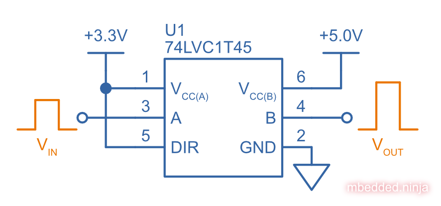
A 74LVC1T45 voltage-level translator IC being used to voltage translate a 3.3V logic-level signal to a 5.0V voltage domain.
Directionality (Unidirectional, Bidirectional, Auto-directional)
The directionality of a voltage-level translator is ability to transfer signals from side A to side B or versa. Unidirectional translators only translate signals in one, fixed direction, such as A to B (side A will always be inputs, side B will always be outputs). Some have a configurable direction with a DIR pin. Some have OE pins. Some have auto-direction sensing with no DIR pin.
How Does Auto-Direction Work?
Auto-direction voltage-level translator ICs use a clever technique to remove the need for a direction pin to specify which side is an input and which side is an output. They work by driving pins with a weak signal (e.g. a CMOS totem-pole driver but with a \(4k\Omega\) resistor in series with the output2) that can be overridden by an external signal.
To fix the problem of these weak drives causing slow edge transitions, one shot timers monitor each side for rising or falling-edges. On a transition, the one shot timers momentarily turn on a strong drive (standard CMOS totem-pole) to create a fast transition. The timer quickly expires, turning of the strong drive and letting the weak drive take over until the next transition.
![Architecture of a single cell inside the TXB0104 IC, showing how the auto-direction sensing circuitry works[^bib-ti-txb0104-ds].](https://blog.mbedded.ninja/electronics/components/voltage-level-translation/ti-txb0104-auto-direction-sensing-architecture.png)
Architecture of a single cell inside the TXB0104 IC, showing how the auto-direction sensing circuitry works2.
Powered Off Protection (IOFF)
Powered off protection is activated when one or more of the power rails is at \(0V\). Texas Instruments commonly uses the name \(I_{OFF}\) to describe this feature.
![Circuit showing how a CMOS "totem-pole" driver is modified to provide "powered off protection". Addition diode added between the substrate and the source of the P-channel MOSFET as circled, which prevents current from the output flowing back to (V_{CC}) in the case that the power rail is at (0V)[^bib-ti-powered-off-protection][^bib-ti-logic-in-live-insertion-apps].](https://blog.mbedded.ninja/electronics/components/voltage-level-translation/cmos-powered-off-protection-circuit-ioff-ti.png)
Circuit showing how a CMOS “totem-pole” driver is modified to provide “powered off protection”. Addition diode added between the substrate and the source of the P-channel MOSFET as circled, which prevents current from the output flowing back to (V_{CC}) in the case that the power rail is at (0V)34.
Propagation Delay
Generally, you want voltage-level translator ICs to have a low propagation delay (commonly abbreviated as \(t_{pd}\)). Most voltage-level translator circuits have a propagation delay between 0.4ns (really fast) and 20ns (quite slow, but still fast enough for many applications).
Clamping Diodes
NXP’s LV, HC, and HEF families have input clamping diodes to VCC and can be used with current-limiting resistors for high-to-low level translation5. Voltage translation: How to manage mixed-voltage designs with NXP level translators.
Four-Port MOSFET with Gate Bias Voltage-Level Translators
Four-port MOSFET with gate bias voltage-level translators (this isn’t their official name, but I had to come up with something!) are voltage-level translators which use a single four-port N-channel MOSFET (substrate connected to ground) between each A and B pin (they don’t have totem-pole drivers). The gate is driven to cleverly found “bias voltage” which allows bi-directional voltage-level translation to happen (with a caveat: sometimes you need pull-ups). They are bi-directional without the need for any DIR pin nor auto-directional sensing circuitry.
- Inherently bi-directional.
- B-side voltage rails must always be higher than A-side voltage rail by some threshold.
- Under certain conditions, relies on a resistor pull-up to make the output go high, limiting maximum signal transition rates.
The LSF family of level translators is one such example (available from many manufacturers).
![Internal schematic for the LSF family of translators[^bib-ti-bias-circuit-lsf-family].](https://blog.mbedded.ninja/electronics/components/voltage-level-translation/lsf-family-level-translator-bias-circuit.png)
Internal schematic for the LSF family of translators6.
The voltage rail on the B-side must always be higher than the voltage rail on the A-side for this style of translator to work properly.
Examples
74LVC1T45Z6-7: Diodes Incorporated, 1-bit
\(I_{OFF}\) is activated when one or more of the power rails is at \(0V\).
![The pinout for the single bit Diodes Inc 74LVC1T45Z6-7 voltage translator in the SOT-563 package[^bib-diodes-inc-74lvc1t45z6-7-ds].](https://blog.mbedded.ninja/electronics/components/voltage-level-translation/74lvc1t45-diodes-inc-voltage-translator-pinout.png)
The pinout for the single bit Diodes Inc 74LVC1T45Z6-7 voltage translator in the SOT-563 package7.
TXB0104
| Manufacturer | Texas Instruments |
| Manf. Part Num. | TXB0104 |
| Topology | Totem-pole |
| Num. Bits | 4-bit |
| Auto-direction | Yes |
| Voltage, \(V_{CCA}\) | 1.2-3.6V |
| Voltage, \(V_{CCB}\) | 1.65-5.5V |
| Package | BGA-12, SOIC-14, QFN-12, |
| Cost | US$1.64 (TXB0104D, quantities of 100) |
The Texas Instruments TXB0104 is a popular 4-bit, auto-directional voltage level translator that comes in a number of different packages, including larger SOIC-14 packages all the way down to BGA-12.
SparkFun makes a breakout board for this IC, the SparkFun Voltage-Level Translator Breakout - TXB0104 (part num. BOB-11771).
![The SparkFun breakout board for the TXB0104[^bib-sparkfun-txb0104-breakout].](https://blog.mbedded.ninja/electronics/components/voltage-level-translation/sparkfun-txb0104-voltage-level-translator-breakout.png)
The SparkFun breakout board for the TXB01048.
Suppliers
Confusingly, voltage level translators can be found in two separate sections (both under the Logic section) on DigiKey:
. Integrated Circuits (ICs) > Logic - Buffers, Drivers, Receivers, Transceivers. One example is https://www.digikey.com/en/products/detail/nexperia-usa-inc/74AUP1T45GW-125/1300776. . Integrated Circuits (ICs) > Logic - Translators, Level Shifters. One example is https://www.digikey.com/en/products/detail/diodes-incorporated/74lvc1t45z6-7/4898825.
References
Nexperia. Voltage translators (level-shifters) (product page). Retrieved 2022-03-17, from https://www.nexperia.com/products/analog-logic-ics/asynchronous-interface-logic/voltage-translators-level-shifters/. ↩︎
Texas Instruments (2020). TXB0104 4-Bit Bidirectional Voltage-level Translator With Automatic Direction Sensing and ±15-kV ESD Protection (datasheet). Retrieved 2022-03-18, from https://www.ti.com/lit/ds/symlink/txb0104.pdf. ↩︎ ↩︎
Shreyas Rao (2016, Nov 2). Logic gates and switches with Ioff or powered-off protection: empowering you to power down (blog post). Texas Instruments. Retrieved 2022-03-13, from https://e2e.ti.com/blogs_/b/analogwire/posts/logic-gates-and-switches-with-ioff-empowering-you-to-power-down. ↩︎
Jose M. Soltero and Ernest Cox (2002, Jan). SCEA025: Logic in Live-Insertion Applications With a Focus on GTLP (Application Report). Texas Instruments. Retrieved 2022-03-13, from https://www.ti.com/lit/an/scea026/scea026.pdf. ↩︎
NXP (2014, May). Voltage translation: How to manage mixed-voltage designs with NXP level translators. Retrieved 2022-03-11, from https://www.nxp.com/docs/en/nxp/brochures/75017511.pdf. ↩︎
Texas Instruments. Understanding the Bias Circuit for the LSF Family (video). Retrieved 2022-07-04, from https://training.ti.com/tlm-lsf-bias. ↩︎
Diodes Incorporated (2018, Oct). 74LVC1T45: Single Bit Dual Power Supply Translating Transceiver With 3 State Outputs. Retrieved 2022-03-11, from https://www.diodes.com/assets/Datasheets/74LVC1T45.pdf. ↩︎
SparkFun. SparkFun Voltage-Level Translator Breakout - TXB0104 (product page). Retrieved 2022-03-18, from https://www.sparkfun.com/products/11771. ↩︎
Authors


This work is licensed under a Creative Commons Attribution 4.0 International License .
Related Content:
- Shift Registers
- Peltiers (Thermoelectric Cooler)
- Electropermanent Magnets (EPMs)
- Neon Sign Transformers
- PROFIBUS