RS-485 Protocol
| Date Published: | |
| Last Modified: |
Overview
The RS-485 communication protocol is a differential, multi-drop, half-duplex, two-wire communication protocol. It was formally specified in 1983 by the Electronics Industries Association (EIA).
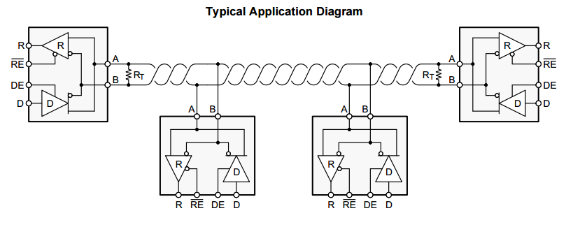
A typical RS-485 network setup, using a standard RS-485 to UART transceiver at each node (in this case it is the TI SN65HVD72). Image from http://www.ti.com/.
It is a very common protocol used in industry for between-room control system to sensor communication.
| Property | Value |
|---|---|
| Name | RS-485 |
| Drive Mode | Differential |
| Multi-drop | Yes |
| Duplexity | Half-duplex |
| Max. Data Rate | 10Mbps |
| Max. Bus Length | 1.22km (@ 100kbps) |
It is not commonly used for intra-board communication (i.e. between two devices on the same PCB) because in these scenarios there is normally no need for the noise immunity and transmission distances RS-485 provides, and communication protocols such as UART, SPI and I2C are more prevalent.
A common and cheap way to implement RS-485 are to use half-duplex transceivers. Examples are the SP485 (cheap), or the SP4082 (slightly more expensive, but with slew-rate limiting and ESD protection).
Some of the receivers have slew-rate limiting to reduce emissions, at the cost of having a lower maximum data rate (typically around 250kbps). Some also have built-in human body ESD protection (15kV), so you don’t have to add external TVS diodes (which normally validates the increase in price you pay for the chips with this feature).
Standards
The TIA/EIA 485 standard governs the RS-485 protocol specifications.
The RS-485 standard only defines the electrical specifications of the interface, and does not specify the type of connector to be used, the cable, the pinout, or the messaging protocol/data structure.
Thus, the RS-485 can be incorporated into higher-level standards which specify things such as the messaging protocol, and use RS-485 to define the physical layer.
Transmission Distances
Because RS-485 is a differential communication protocol, it can achieve far greater communication distances than say, UART, I2C or SPI.
A distance of 1.22km (4000 feet) is achievable at a data rate of 100kbps.
Baud Rate
RS-485 transceivers usually top out at about 50-100Mbps.
Node Count
Higher baud rate transceiver ICs usually support a lower number of total nodes on the RS-485 bus.
RS-485 introduces the term unit load. A unit load is a specified load impedance on the RS-485 bus. Transceivers are rated by the equivalent unit loads of impedance they introduce when connected to the bus.
| Unit Load | No. of Nodes | Min. Receiver Input Impedance |
|---|---|---|
| 1 | 32 | \(12k\Omega\) |
| \(\frac{1}{2}\) | 64 | \(24k\Omega\) |
| \(\frac{1}{4}\) | 128 | \(48k\Omega\) |
| \(\frac{1}{8}\) | 256 | \(96k\Omega\) |
Termination Resistors
The TIA/EIA 485 standard does not specifically state what the characteristic impedance of the twisted-pair cable should be, nor the value of the termination resistors. However, it does provide recommendations, and states that the twisted-pair cable should have a characteristic impedance of \(120\Omega\) whenever possible.
This implies that \(120\Omega\) termination resistors should be used with this twisted-pair cable. Termination resistors of 120R connected between the two differential lines work well at reducing reflections along long cables.
Receiver Hysteresis
Receiver hysteresis is normally around 80mV.
Standard Pinout
There is somewhat of a standard pinout for RS-485 transceivers in 8-pin component packages as follows:
| Pin Number | Pin Name | Pin Description |
|---|---|---|
| 1 | R, RO | Receiver data output. |
| 2 | nRE, RE* | Active-low receiver out enable. |
| 3 | DE | Active-high RS-485 line driver enable. When high, the IC will be driving the RS-485 A and B wires, when low the A and B pins are put into high-impedance and the IC acts as a RS-485 receiver. |
| 4 | D, DI | Driver data input. If the driver outputs are enabled (DE high), then a low on DI drives A low and B high, while a high on DI drives A high and B low. |
| 5 | GND | Ground. |
| 6 | A | RS-485 differential line A. |
| 7 | B | RS-485 differential line B. |
| 8 | \( V_{CC} \) | Supply voltage. |
8-pin packages that RS-485 transceivers come include DIP-8, SOIC-8, TSSOP-8 and MSOP-8. Example transceivers that follow this “standard” include the Texas Instruments DS485, Linear Technology LTC1480.
Higher-Level Protocols
Do you need a higher-level communication protocol that works over a UART connection? See the SerialFiller library on GitHub (written in C++). SerialFiller uses a publish/subscribe mechanism and works well on point-to-point serial connections such as UART.
PROFIBUS can use RS-485 as it’s physical layer.
Differential Voltage Specs
The RS-485 specification states that the transmitter must produce a differential voltage of at least ±1.5V when loaded, and the receiver must receive a differential voltage of at least ±200mV.
The waveform below shows the voltage on the A and B nets of a RS-485 bus when operating normally at 115200 baud.
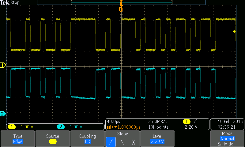
The typical appearance of the voltages on the A (top) and B (bottom) nets of a RS-485 bus under normal operating. This was operating at 115200 baud.
The standard also states that the driver is not allowed to produce a differential voltage of more than ±6V.
Common-Mode Voltage
Most transceivers can withstand a constant single-ended voltage of around ±15V on each of the A and B wires (the allowed transient voltage can be much higher).
Specialised TVS Diodes
Dedicated TVS diode components exist for voltage-spike suppression on RS-485 data lines.
They usually are a bidirectional TVS diode (or diode array) with asymmetric breakdown voltages, that match the maximum voltage specifications of +12V and -7V for RS-485 data lines.
The +12V and -7V limits arise from the section of the RS-485 spec which states that up to a 7V ground difference is allowed between any two devices on a RS-485 bus. This, coupled with the spec that allows a single-ended voltage range of 0-5V to be applied to either of the bus nets, gives a possible voltage range of +12V (7V + 5V) to -7V (-7V + 0V).
One such example is the Semtech SM712 diode array. Below is an image of the components internal schematic.
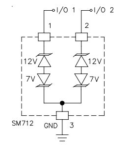
The SM712 TVS diode array, a diode array with asymmetric breakdown voltages, specifically designed for protecting RS-485 data lines. Image from http://www.semtech.com/.
SAE J1708
SAE J1708 is a communications protocol standard introduced by SAE in 1986. It was intended to be used for serial communications between ECUs on heavy duty vehicles. Today, the CAN Bus protocol is usually used instead of SAE J1708.
The hardware used for SAE J1708 is usually a RS-485 transceiver that is wired for open collector operation. Transmission of bits is done through controlling the driver enable pin of the transceiver (rather than using the data in (DI) pin, which is used during normal RS-485 operation).

A standard RS-485 transceiver with a modified bus connection to provide open collector (wired OR) arbitration for the SAE-J1708 bus. Image adopted from content found at http://www.ti.com/lit/an/snla038b/snla038b.pdf.
The receiver is always enabled (RE* pin connected to ground) so that the bus state can be checked on every attempted write of a bit. The bus state needs to be compared with the intended write bit, if they are different, another node is also writing on the bus and this bus has lost arbitration.
The modification to RS-485 essentially allows you to operate a multi-master (multi-point) configuration.
This configuration means you will no longer be RS-485 compliant.
References
Authors


This work is licensed under a Creative Commons Attribution 4.0 International License .
Related Content:
Tags
- RS-485
- communication protocols
- transmitters
- receivers
- data
- bus
- serial
- nodes
- SAE J1708
- transmission distances
- PROFIBUS
- Process Field Bus
- PNO
- PI
- FDL
- Fieldbus