CAN Protocol
| Date Published: | |
| Last Modified: |
Overview
The CAN (Controller Area Network) protocol is a serial-based, multi-master digital communication protocol originally developed by BOSCH.
The CAN bus logo. Image from www.bosch.com.
It was initially developed for use in the automotive industry. It provides priority-based message arbitration by utilizing dominant (driven by transmitter) and recessive (pulled together through bus termination resistors) bit levels.
Protocol Versions
- CAN2.0A (ISO 11898): Standardized as ISO 11898 in 1993. Supports standard frames (11-bit identifiers).
- CAN2.0B: Released in 1995. Supports both standard and extended frames (11-bit and 29-bit identifiers). CAN 2.0B is backwards compatible with CAN 2.0A, with the exception that the CAN 2.0A controllers have to be updated to be aware of CAN 2.0B and have the passive feature. If they don’t, CAN 2.0A controllers will flag CAN 2.0B extended frame messages as errors.
- CAN-FD: The “CAN with Flexible Data-rate” protocol. Protocol updated to change the meaning of different bits in the arbitration sequence, as well as the ability for the bit rate to be changed during the data part of the packet (generally increased to increase bit rate).
CAN Bus Voltages
The CAN bus transmits 1 and 0’s across a differential pair of wires. A recessive logic 1 is when the driver is not “driving” the bus, and therefore there should be almost no voltage differential across CAN_H and CAN_L. A dominant logic 0 bit is when the transmitting node drives CAN_H high and CAN_L low, generally resulting in a few volts of difference between CAN_H and CAN_L.
Bit Rate And Transmission Distances
The following equation can be used as a rule-of-thumb to calculate the maximum transmission speed for distances larger than 50m.
$$\begin{align} BR\times L\leq 60 \end{align}$$where:
\(BR\) = bit rate (in MBit/s)
\(L\) = length (in m)

A value \(5ns/m\) is typically used for the propagation time of the CAN bus signal down the twisted-pair cable when calculating maximum baud rates and/or cable lengths. A table of common distances/transmission rates is shown below. These cable lengths are for the cable trunk, and not for stubs.
| Speed | Distance | Comment |
|---|---|---|
| 10kb/s | 5000m | Used by the SAE J1850 standard. |
| 20kb/s | 2500m | |
| 50kb/s | 1000m | |
| 125kb/s | 500m | Default speed for CANopen. |
| 250kb/s | 250m | Used by the J1939 standard. |
| 500kb/s | 100m | |
| 800kb/s | 50m | |
| 1Mb/s | 25m |
CAN bus lengths are restricted because all nodes need to be able to sample the bus (and read back a correct result) during the same bit time. They need to do this for two reasons:
- Bus arbitration: Nodes need to know if they have lost arbitration of the bus (another node has sent a dominant value whilst they have sent a recessive value).
- Acknowledge bit: The transmitter needs to read the acknowledge value back from the receiver within the period for the acknowledge bit in every frame.
Propagation delays due to long buses will eventually result in nodes sampling the wrong bit, hence limiting the maximum bus length.
Stubs
There is a significant amount of contradictory information online on what CAN stub lengths are permissible. The various opinions are:
- TI’s SLLA270 states to minimize reflections, lengths of stubs should not exceed 1/3 of the critical length of a bus1. The critical length is determined by the transition time of bits on the bus (which is determined by the driver), and the speed at which signals propagate down the bus.
- Bueno Electric’s Maximum Cable Length For a CAN Bus page2 gives a maximum cable stub length of 0.3mm for all speeds from 50kb/s to 1Mb/s.
- and OnSemi3 give the following rule: $$\begin{align} L_{STUB_MAX} = \frac{T_{PROP_SEG}}{50 \cdot T_{PROP(BUS)}} \end{align}$$
Some CAN bus drivers provide pins so that you can adjust their slew rate.
Termination Resistors
For high-speed transmission on the CAN bus, termination resistors are required between the CAN_H and CAN_L wires at both ends of the cable. However, make sure to only add them at the ends of the cable, any CAN devices connected partway along the bus should not have termination resistors. For a CAN bus in which devices may be arbitrarily connected and disconnected, it is common practise to add switchable termination, which can be connected manually with a typical mechanical switch or automatically controlled by firmware/software using an MOSFET-based switch or similar. Although required by the standard, termination resistors are not typically required for the CAN bus to function at slow speeds over small distances.
Adding a single termination resistor of 120R at each end of the bus is called standard termination. Sometimes a decoupling capacitor is also added in conjunction with the termination resistors. This is called split termination4, as you have to use two termination resistors instead of one, with the capacitor “splitting” them in two. Using this combination of resistors and capacitor makes a low-pass filter for the common-mode noise on the bus, which has a corner frequency given by the equation4:
Isolation
When CAN bus receivers are incorporated onto PCBs with microcontrollers and other digital/analogue circuitry, it is common practise to isolate the CAN circuitry so that noise and voltage spikes from the CAN bus do not damage the circuitry.
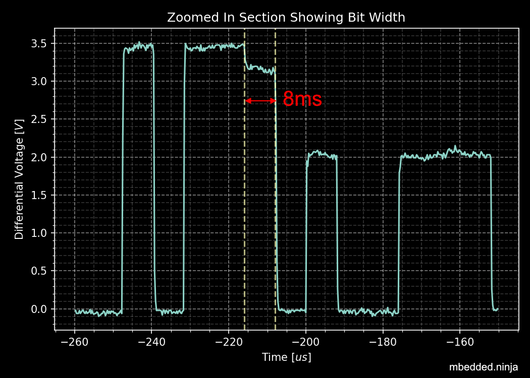
Connectors
The CiA DS-102 standard defines CAN bus pin assignments for the ubiquitous serial DE-9 connector:
This pin layout is also used for other CAN standards such as CANopen.
Arbitration
The CAN network uses priority-based message arbitration. Message arbitration is required because the CAN networks supports a multi-master bus configuration (i.e. no one master node controls all communication, any node is freely able to attempt to transmit at any time). Arbitration works like such:
The drivers to the CAN line(s) are open-drain. This means that if a node writes a 0 (dominant), it will over-write a 1 (recessive). This is also called a wired AND configuration.
Wired AND is a good way to allow physical arbitration to take place when multiple nodes to attempt to communicate at the same time. The I2C bus is another protocol that uses this technique.
- Both nodes starts to transmit, but each message has a different message ID. Both nodes also monitor the state of the bus.
- At some point in time, because of the different message IDs, one node will try to transmit a 0 (dominant) while the other will try to transmit a 1 (recessive).
- The node transmitting the 0 will detect the bus as 0, and will continue transmitting.
- The node transmitting the 1 will detect the bus as 0, indicating that it has lost control (remember a 1 is recessive, and get’s “overwritten” by a 1 due to the open-drain drive). This node will back-off, stop transmitting, and try again later.
After understanding the arbitration process explained above, it’s clear that CAN messages with lower numbered identifiers will therefore take priority over those with higher identifiers.
Car thieves have been cleverly using a special transmitter that also drives to the recessive level to override other messages on a vehicles CAN bus network, which has allowed them to break in and steal cars by accessing the CAN bus from the front headlights5. See CAN Injection: Keyless Car Theft for more info.
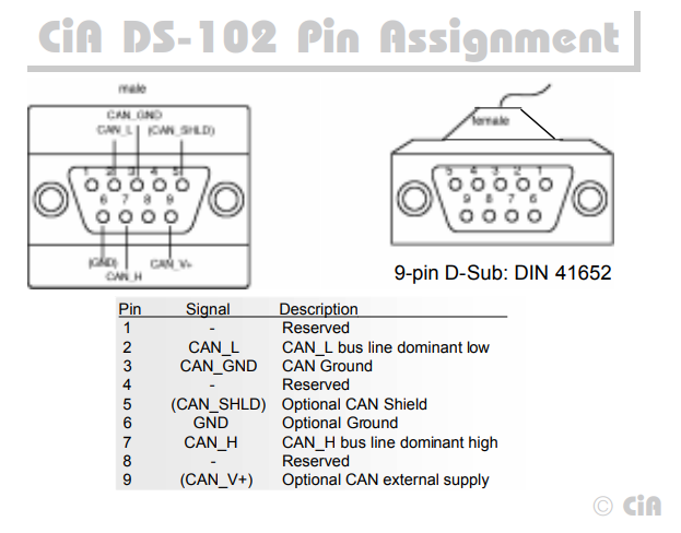
The below image shows arbitration happening with a real-world scope capture, by showing the changing dominant bus voltage as driving transceivers lose arbitration and “drop” off the bus.
Scope capture showing arbitration happen in real life! This scope was connected at some point on a long CAN bus with many transceivers, with a differential probe across the CAN_H and CAN_L wires. Since each transceiver is a different distance away from the measurement point, and there were transceiver from different IC manufacturers on the bus, each one drives the bus to a slightly different dominant voltage as seen by the scope.
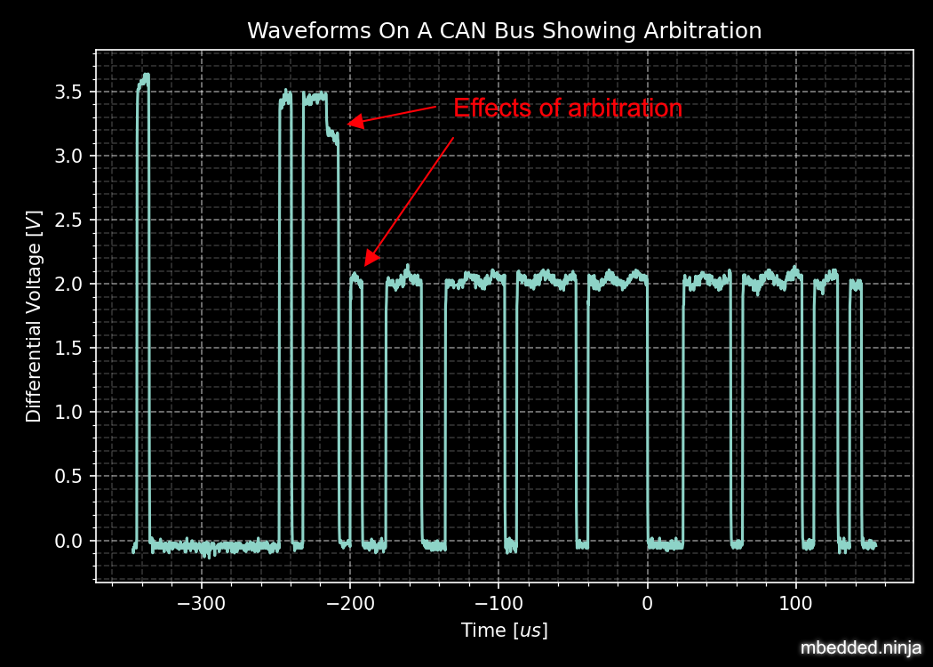
If we zoom in on one of the arbitration events as below we can see it aligns with the bit period of 8us (the CAN bus was running at 125kHz).
Zoomed in view of the above scope capture, showing the width of the arbitration “events” aligns with the bit period of 8us (CAN bus was running at 125kHz).
CAN Bit Timing
The below diagram shows the timing of a single CAN bit. A single CAN bit is broken down into different time segments. Each time segment is defined by an integer number of time quanta (\(t_q\)). Time quanta is determined by the clock provided to the CAN transceiver. This CAN clock is usually provided from a faster system clock by dividing by a programmable pre-scalar. The minimum is 5, but there is usually 8 or more \(t_q\) per CAN bit. The time quanta is the smallest amount of time that the CAN transceiver can adjust it’s timing by (i.e. it’s resolution).
. SYNC_SEG: This is always \(t_q\). The transceiver expects the bit transitions to occurs during this time period. If they don’t, the transceiver performs [^_resynchronization, resynchronization] to re-align itself.
. PROP_SEG: This is the time segment of the bit in which it is expected that the transition will finish propagating to all nodes. It is the two way propagation that matters, i.e. the total time for the transmitted bit to propagate to all nodes and then the nodes response to propagate back. This has to include the propagation time of the signal on the wire (5ns/m is a good approximation), plus propagation delay through the CAN transceivers.
. PHASE_SEG_1: Phase segment 1.
. SAMPLE_POINT: This is the point in time in-between PHASE_SEG_1 and PHASE_SEG_2 at which the transceiver samples the value on the bus (recessive or dominant).
. PHASE_SEG_2: Phase segment 2.

Only one sample point is shown above, however some transceivers support sampling the bus three times to improve noise resiliency – once at the sample point as shown in the diagram, once at \(1t_q\) before this point and once 1TQ after this point. Majority voting is then used to determine the state of the bus.
| Segment | Duration |
|---|---|
| SYNC_SEG | \(1t_q\) |
| PROP_SEG | \((1..8)t_q\) |
| PHASE_SEG_1 | \((1..8)t_q\) |
| PHASE_SEG2 | \(max(IPT, t_{PHASE\_SEG\_1})\) |
IPT is the information processing time.
Most CAN transceivers have the lengths of the bit segments configured so that they sample the bit between 75% and 87.5% of the time between the start of one bit and the beginning of the next bit6.
Because any CAN node may sample the bus as soon as PROP_SEG is over, the two way propagation of the signal between any two nodes on the bus must occur before the end of PROP_SEG. The below figure illustrates this between two nodes, one which is the transmitter and another which is the receiver. The signal has to propagate back from the receiver to the transmitter within this time because the transmitter needs to read back values from the bus during arbitration and the acknowledge bit.

Diagram showing why the two-way propagation of the bit must occur between any two nodes before the end of the PROP_SEG.
The main limiting factor on the total bus length at a specific baud rate is the stabilization time for a dominant to recessive bit transmission on the bus. Because it is not driven, the termination resistors play the role of bringing the differential voltage back to the recessive state. The time it takes for the resistors to do this is primarily dependent on the amount of capacitance on the bus. This in term determines the maximum length of the bus, as adding additional twisted pair cable increases the capacitance.
Synchronization
Hard Synchronization
Hard synchronization occurs on the first recessive-to-dominant transition (the start-of-frame, or SOF) when the bus is idle7.
Resynchronization
Resynchronization is done throughout a CAN frame to maintain the initial synchronization that was done with the hard synchronization. Local oscillator drift (frequency differences between the oscillators driving each node) will cause the bit timing between each node to drift. Resynchronization aims to periodically correct for this.
Resynchronization is done on the recessive-to-dominant transitions that occur during a frame. The actual measured transition compared to where it is expected to occur, which is during the SYNC_SEG (see CAN Bit Timing for a diagram illustrating these segments). Depending on whether the actual transitions occurs before, during or after the SYNC_SEG, time is either added to the PHASE_SEG_1 segment or subtracted from the PHASE_SEG_2 segment. The following rules are used:
- Transition occurs before
SYNC_SEG:TQis subtracted fromPHASE_SEG_2. - Transition occurs during
SYNC_SEG: No adjustment. - Transition occurs after
SYNC_SEG:TQis added toPHASE_SEG_1.
The amount of TQ added or subtracted depends on the synchronization jump width (SJW, also called resynchronization jump width or RJW8). The SJW is usually a configurable (programmable) parameter of the CAN transceiver.
TIP: Remember that the dominant state is driven, hence the recessive-to-dominant transition is always going to be sharper then the dominant-to-recessive transition, hence why the former edges are used for resynchronization.
A transmitting node will not resynchronize on a positive phase error. This means that a transmitting node will not resynchronize due to propagation delays of it’s own message. Instead, it is left up to the receivers to resynchronize.
Encoding
The CAN bus uses bit-stuffed NRZ encoding.
Any sequential sequence of 5 bits of the same type requires the transmitter to insert (stuff) a bit of the opposite polarity. Consequentially, the receiver has to remove this bit from the incoming data stream, as it is not part of the original data.
This bit stuffing prevents serious clock drift when there a long sequences of either 0’s or 1’s transmitted on the bus. There is no separate clock signal (which is why the CAN bus can be called an asynchronous protocol), so the clock is recovered from the data.
Frames
Frame Types
- Data Frames: Used to transmit a data payload of up to 8 bytes. Very similar frame structure to a remote frame.
- Remote Frames: Used to request data and possibly implement a request-response system (the CAN standard does not prescribe what they should be used for). Contains no data payload itself, and very similar frame structure to a data frame. In practise, remote frames are used very little in industry.
- Error Frames: Transmitted when a node encounters an error during communication. An error frame contains only an error flag and an error delimiter. Error counters on numerous nodes are generally incremented when they detect error frames on the bus.
- Overload Frames: If a CAN node receives messages faster than it can process them, then the CAN node can generate Overload Frames to delay the next data/remote frame. An overload frame contains two fields, an overload flag consisting of 6 dominant bits (hence it wins arbitration and prevents another data/remote frame), and then an overload delimiter of eight recessive bits. Error counters are not incremented when overload frames are detected9.
Frame Structure
Dominant bits are logic level 0, while recessive bits are logic level 1.
Standard Data/Remote Frame (11-bit Identifier)

SOF bit: A dominant start of frame bit marks the start of a message. It is used to synchronize all the nodes on a bus after being idle. Transmitted by the sender.
11-bit Identifier: This 11-bit value is used to identify the contents packet. It is also used to prioritize packets, and identifiers with lower values will have higher priorities. It is important to note that the identifier is NOT a destination node address. It is purely used to identify the type of message, and multiple CAN nodes may be listening/receiving this type of message.
RTR bit: The Remote Transit Request bit differentiates between data and remote frames (a remote frame is a request for data). In data frames, this bit is dominant and in remote frames this bit is recessive. Thus, data being returned from a request always has a higher priority than a packet requesting the data (with the same identifier).
IDE bit: The Identifier Extension bit distinguishes between standard and extended frames. In standard frames this bit is dominant, in extended frames this bit is recessive.
r0 bit: This bit is reserved for future CAN bus standards user. Always recessive.
4-bit DLC: The 4-bit Data Length Code (DLC) contains the number of bytes that will be transmitted. Since the range of data bytes can vary between 0-8, we need 4 bits to specify this value. DLC values from 9-15 are not allowed.
0-8 bytes Data: This is the data payload. Up to 8 bytes can be sent in a single packet, as long as it is a data frame. For a remote frame, there must be no data bytes.
16-bit CRC: The Cyclic Redundancy Check (CRC) is used to detect errors in the packet. It consists of a 15-bit CRC value followed by a delimiter.
2-bit ACK: The sender sends a recessive value for the first acknowledge bit of the acknowledge field (called the ACK slot). The receiver(s) drives the first acknowledge bit to to the dominant state if it wants to acknowledge the bit. The 2nd bit of the acknowledge field is the ACK delimiter and is driven recessive by the transmitter.
TIP: In the situation when there are multiple receivers, the acknowledge bit will be driven to the dominant by state by 1 or more of the receivers if they acknowledge.
7-bit EOF: The End Of Frame is marked with 7 recessive bits.
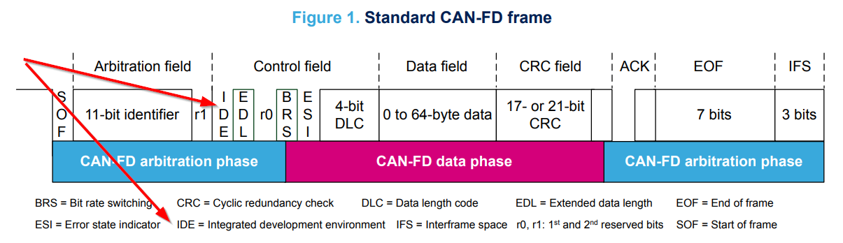
Don’t always believe what you see in datasheets. There is definitely no ‘Integrated Development Environment’ bit in a CAN frame. Image from https://www.st.com/resource/en/application_note/dm00625700-fdcan-peripheral-on-stm32-devices-stmicroelectronics.pdf, accessed 2021-04-19.
Extended Data/Remote Frame (29-bit Identifier)
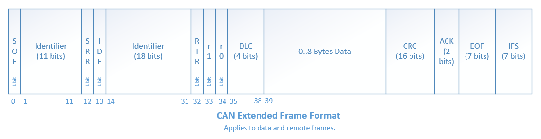
The extended frame is the same as the above standard frame, except for the differences described below:
SRR bit: The Substitute Remote Request bit is transmitted in extended frames at the position of the RTR bit in standard frames. It is always recessive.
IDE bit: The Identifier Extension bit distinguishes between standard and extended frames. In standard frames this bit is dominant, in extended frames this bit is recessive.
r1: An additional reserve bit for extended frames only. Must be recessive.
18-bit Identifier: Another 18-bits that can be used as part of the identifier, giving a total of 29-bits for the identifier in an extended frame. 11-bit identifiers have a higher priority than 29-bit identifiers.
Message Lengths
There are two different message lengths supported by the CAN protocol.
- CAM Base Frame (CAN2.0A)
- CAM Extended Frame (CAN2.0B)
Errors
There are 5 different types of errors defined by the CAN standard10:
- Bit Error: The transmitter monitors the bus level as it sends bits. If the level is not the same as what it is transmitting, a bit error occurs. The one exception to this rule is that no bit errors are raised during the arbitration process as differences are to be expected during this phase. Physical layer error.
- Stuff Error: If 5 consecutive bits of the same level have been transmitted, the transmitter will add a 6th bit of opposite polarity to the transmission (and the receivers remove this 6th bit). A stuff error occurs if 6 or more consecutive bits of the same type are found. Physical layer error.
- Format Error: Some parts of a CAN frame have predefined/fixed levels (incl. the CRC delimiter, ACK delimiter, EOF). If a receiver detects the wrong level at any of these bit locations, a format error occurs. This is a data-link layer error.
- CRC Error: When the computed 15-bit CRC does not match the one received in the message packet, the receiver raises a CRC error. This is a data-link layer error.
- Acknowledge (ACK) Error: All receiving nodes that correctly receive a CAN frame will transmit a dominant level during the ACK bit. The transmitter sends a recessive level during this bit. If the transmitter does not detect a dominant level during this bit, an acknowledgement error occurs. This is a data-link layer error.
All CAN nodes will monitor the bus for the above errors. If a node detects an error, it will transmit an error flag. There is more than one type of error flag, these are explained below.
Dealing With Errors
To prevent fault CAN nodes from from permanently disturbing/blocking a CAN network, the CAN standard defines a somewhat sophisticated fault confinement process that nodes much adhere to. This fault confinement process is usually implemented in CAN controllers/peripherals, such that the main application does not have to deal with this itself (many users of CAN systems may be unaware that these fault confinement processes even exist!).
Each CAN node maintains two error counters, the transmit error counter (TEC) and the receive error counter (REC). A CAN node initially starts out in the Error Active state. When either of the TEC or REC (error counters) goes above 127, the node will transition to the Error Passive state. When the TEC (but not the REC) goes above 255, the node transitions to the Bus Off state. A node will transmit different error flags depending on what error state it is in10:
- In the Error Active state, a node will transmit Active Error flags when it detects an error.
- In the Error Passive state, a node will transmit Passive Error flags when it detects an error. It also has to wait
- In the Bus Off state, a node will not transmit anything at all.
An Active Error flag consists of 6 dominant bits followed by 8 recessive bits. The 6 dominant bits purposefully breaks the bit stuffing rule above (of no more than 5 consecutive bits having the same level), which causes all other nodes to send their own error flag (in response to the violation of the bit stuffing rule).
An Error Passive flag consists only of recessive bits, as to not disrupt any existing communications (i.e. will not block the bus).
Adding/Subtracting From the Error Counters
The rules for adding to or subtracting from the error counters is rather complex11:
- When a receiver detects an error, the REC will be increased by 1, except when the detected error was a Bit Error during the sending of an Active error Flag or an Overload Flag.
- When a receiver detects a dominant bit as the first bit after sending an Error Flag, the REC will be increased by 8.
- When a transmitter sends an Error Flag, the TEC is increased by 8. Exception 1: If the transmitter is Error Passive and detects an ACK Error because of not detecting a dominant ACK and does not detect a dominant bit while sending its Passive Error Flag. Exception 2: If the transmitter sends an Error Flag because a Stuff Error occurred during arbitration, and should have been recessive, and has been sent as recessive but monitored as dominant.
- If the transmitter detects a Bit Error while sending an Active Error Flag or an Overload Frame, the TEC is increased by 8.
- If a receiver detects a Bit Error while sending an Active Error Flag or an Overload Flag, the REC is increased by 8.
- Any node tolerates up to 7 consecutive dominant bits after sending an Active Error Flag, Passive Error Flag or Overload Flag. After detecting the fourteenth consecutive dominant bit (in case of an Active Error Flag or an Overload Flag) or after detecting the eighth consecutive dominant bit following a Passive Error Flag, and after each sequence of additional eight consecutive dominant bits, every transmitter increases its TEC by 8 and every receiver increases its REC by 8.
- After successful transmission of a frame (getting ACK and no error until EOF is finished), the TEC is decreased by 1 unless it was already 0.
- After the successful reception of a frame (reception without error up to the ACK Slot and the successful sending of the ACK bit), the REC is decreased by 1, if it was between 1 and 127. If the REC was 0, it stays 0, and if it was greater than 127, then it will be set to a value between 119 and 127.
- A node is Error Passive when the TEC equals or exceeds 128, or when the REC equals or exceeds 128. An error condition letting a node become Error Passive causes the node to send an Active Error Flag.
- A node is Bus Off when the TEC is greater than or equal to 256.
- An Error Passive node becomes Error Active again when both the TEC and the REC are less than or equal to 127.
- A node which is Bus Off is permitted to become Error Active (no longer Bus Off) with its error counters both set to 0 after 128 occurrence of 11 consecutive recessive bits have been monitored on the bus.
Transmit errors are generally “weighted” more than receive errors because it’s more likely that the transmitter is the one at fault, and hence it will transition to the Error Passive and Bus Off states before the receiving node would.
Many CAN controllers provide status bits and interrupts (when the node transitions to this state) for the following conditions:
- An “error warning”, when at least one of the error counters is above 96.
- When the node is in the “Bus Off state”.
Once a node is in the Bus Off state, there are two ways the node can recover from this12:
- Automatically after 128 occurrences of 11 consecutive ‘recessive’ bits have been monitored on the bus. (BOSCH CAN 2.0B §8.12)
- A node can start the recovery from »bus off« state only upon a user request. (ISO11898-1 §6.15)
In either case, the node has to wait for 128 occurrences of 11 consecutive recessive bits after it has entered the Bus Off state before it is allowed to transmit. This allows 128 messages to pass before a potentially faulty node begins to wreck havoc on the bus again. Generally, the smarter way to handle a node transitioning into the Bus Off state is to disable the auto-retry mechanism (most CAN peripherals allow you to do this), and let the application firmware decide what to do. This would normally meaning waiting for a longer time that 128x11 recessive bits, and only retrying a small number of times before giving up completely.
CAN Controller IP
Most popular FPGA vendors provide pre-licensed (you don’t have to pay anything to use it!) CAN controller IP cores for use within their FPGAs.
Xilinx provides the CAN 2.0B and CAN-FD Controller IP core which is compatible with the Ultrascale, Zynq-7000, 7-series, 6-series and other Xilinx FPGAs.
Standards
CANopen
CANopen was developed for embedded devices in automation systems . It defines the OSI network layers that the basic CAN standards leaves unspecified, which includes the network layer and above.
The CANopen standard is defined by the CiA (CAN in Automation) group. The documents for these standards can be found at https://www.can-cia.org/groups/specifications/. The most important document is CiA 301, which defines the CANopen application layer. If the above link is down, you can view the local cached copy, v4.2.0, accessed June 2020.
All CANopen nodes must have a object dictionary.
FlexRay
FlexRay is a newer protocol that has been designed to overcome some of the limitations of the CAN bus. It supports much longer message data lengths and has improved CRC/error detection. However it is more expensive to implement than CAN as as of June 2020 is still not as popular worldwide as CAN.
ISO 11783
ISO 11783 is title “Tractors and machinery for agriculture and forestry—Serial control and communications data network” and is commonly called ISOBUS. It is based of the SAE J1939 protocol (which includes the CAN bus).
ISO 11898
ISO 11898 is a widely followed basic CAN standard, defining parts of the physical and data link layers. There are many different versions of this standard:
- ISO 11898-1:2015 - Specifies data-link layer and physical signalling
- ISO 11898-2:2003 - Specifies the high-speed transmission (up to 1MBit/s) medium access unit (MAU). This has been revised by ISO 11898-2:2016.
- ISO 11898-2:2016 - Specifies the high-speed physical media attachment (HS-PMA) component for the CAN bus.
- ISO 11898-3:2006 - Specifies low-speed, fault tolerant CAN bus information transfer between road vehicles.
ISO 11898 specifies a maximum bus length of 1km, but does allow the use of bridge-devices or repeaters to extend the bus beyond this13.
Related to ISO 11898 is ISO 16845, which details test suites and test requirements for checking CAN bus/controller conformance to the specs.
NEMA 2000
A communication protocol for ships which is based on the CAN standard.
PeliCAN
PeliCAN is a CAN controller “mode” named by NXP with the arrival of their SJA1000 stand-alone CAN controller ICs, which were a successor to the PCA82C200 CAN controller ICs (BasicCAN). PeliCAN supports all of the frame types defined by CAN 2.0B.
PeliCAN mode extensions include:
- Error counters
- Error interrupt
- Single-shot transmission (no re-transmission)
- Listen only mode
- Hot plug-in support
- Acceptance filter extension
- Self reception support (can receive messages sent by self)
SAE J1939-11
Uses a shielded twisted pair. Used in trucks, agricultural and industrial equipment.
Licensing
The CAN protocol and CAN FD protocol are protected with IP rights by Bosch. Any CAN IP modules for a FPGA or ASIC (including self-developed ones!!!), or fixed hardware CAN IP peripherals for microcontrollers must be licensed.

A screenshot of the CAN bus licensing fee details from Bosch. Image from http://www.bosch-semiconductors.de/media/automotive_electronics/pdf_2/ipmodules_3/can_protocol_license_1/Bosch_CAN_Protocol_License_Conditions.pdf.
TVS Diodes
There are TVS diode components specifically designed for CAN bus ESD suppression. Single diode 2-pin packages or double (termed a diode array) TVS diode 3-pin packages are common. Common standoff voltages are \(12V\) and \(24V\) and common power dissipations are \(200-500W\).
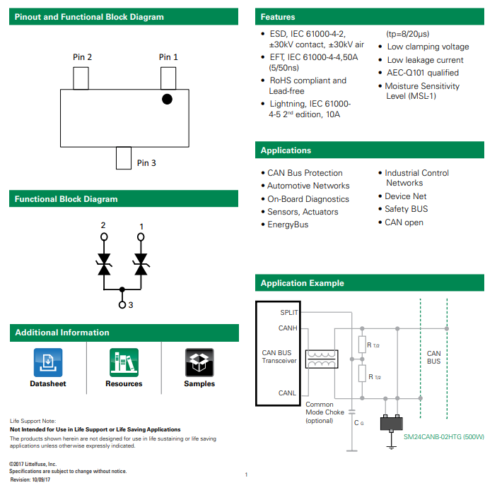
Block diagram and application example for the CAN bus AQ24CANFD TVS diode from LittelFuse. Image from https://www.littelfuse.com/~/media/electronics/datasheets/tvs_diode_arrays/littelfuse_tvs_diode_array_aq24canfd_datasheet.pdf.pdf, acquired 2021-04-27.
NoCAN
NoCAN is a communications protocol that is built on-top of the CAN bus. It provides a layer of abstraction on-top of a 125kHz CAN bus which adds publish-subscribe based messaging and automated address assignment. With many wireless options available for IoT devices, NoCAN was borne out the idea that there is a need for an easy-to-use wired communications solution for IoT devices. The protocol was created by Omzlo and was funded in part by a KickStarter campaign in 2019.

NoCAN only uses the CAN Extended Mode, which supports a 29-bit ID, and up to 8 bytes of message data. However NoCAN provides the ability to send up to 64 bytes of data per message by chaining together up to 8 CAN messages (also called frames). For every NoCAN bus, there must be one (and only one) “special” node called a Network Manager, and one or more “standard” nodes. NoCAN also offers defines message formats for firmware update and bootloader control over the CAN bus.
NoCAN supports up to 128 nodes on a CAN bus.
DeviceNet (IEC 62026-3)
DeviceNet is a network/messaging layer on top of the CAN bus protocol. It is commonly used in the automation industry.
DeviceNet supports the following baud rates:
- 125Kbits/s
- 250Kbits/s
- 500Kbits/s
DeviceNet cable typically consists of two shielded, twisted pairs. One pair has a larger wire diameter for carrying power, and the other pair with a smaller wire diameter is for the data.
CAN Bus Transceivers
TN82527
The TN92527 (a.k.a just the 82527) is an older CAN transceiver made by Intel14. It was Intel’s first CAN controller that supported CAN Specification 2.0.
NXP
NXP makes a whole suite of CAN transceivers all starting with the part number TJA1. You can view their portfolio at https://www.nxp.com/products/interfaces/can-transceivers:MC_53485. A common transceiver for “low-speed CAN” is the TJA1054. NXP also make “Secure CAN” transceivers such as the TJA115x (these don’t use cryptography but rather hardware ID validation with passlists/blocklists)15.
![The basic principle of the TJA115x Secure CAN range of CAN transceivers from NXP[^bib-nxp-tja115x-secure-can].](https://blog.mbedded.ninja/electronics/communication-protocols/can-protocol/nxp-tja115x-secure-can-application-principle.png)
The basic principle of the TJA115x Secure CAN range of CAN transceivers from NXP15.
TJA1052i
- Speed: 5Mbps
- Package: SOIC-16W
- Datasheet
Texas Instruments ISO1044BD
CAN Bus Controllers
A CAN bus Controller is an IC which contains all the logic and data processing ability to send and receive CAN bus messages. They typically do not have CAN_H and CAN_L outputs, but rather just logic-level TX and RX pins that need to be connected to a separate CAN transceiver (there are a few which do feature an integrated transceiver, such as the Texas Instruments TCAN4550).
PCA82C200
| Parameter | Value |
|---|---|
| Manufacturer | Phillips (now NXP) |
| Part Number | PCA82C200 |
| Protocols | CAN2.0A |
| Interface | Parallel |
| Integrated Transceiver | No |
| Package | DIP-28 |
The PCA82C200 is “the” classic original CAN controller. It used a parallel interface (8 address lines + control lines). The Phillips datasheet I found for this part dated back to October 199016.
![Block diagram of the PCA82C200 CAN controller IC[^bib-philips-pca82c200-ds].](https://blog.mbedded.ninja/electronics/communication-protocols/can-protocol/pca82c200-can-controller-block-diagram.png)
Block diagram of the PCA82C200 CAN controller IC16.
SJA1000
The SJA1000 is pin compatible with the PCA82C200 (it comes in either a DIP-28 (SJA1000) or SOIC-28 (SJA1000T) package). It has PeliCAN mode extensions.
MCP2510
| Parameter | Value |
|---|---|
| Manufacturer | Microchip |
| Part Number | MCP2510 |
| Protocols | CAN2.0A, CAN2.0B |
| Interface | SPI |
| Integrated Transceiver | No |
| Package | SOIC-18, TSSOP-20 |
Significant errata for this part.
TCAN4550
| Parameter | Value |
|---|---|
| Manufacturer | Texas Instruments |
| Part Number | TCAN4550 |
| Protocols | CAN2.0B, CAN FD |
| Interface | SPI |
| Integrated Transceiver | Yes |
| Package | QFN-20 |
The TCAN4550 has an integrated transceiver, so you don’t have to use a separate IC.
CAN Bus Microcontroller Peripherals
CAN bus transceivers only do the work of converting the CAN bus differential signal into two single-ended signals (one for transmit, one for receive). To use the CAN bus, you also need a CAN bus controller, which is typically implemented as a CAN bus peripheral within a microcontroller (although you can get dedicated CAN bus controllers which can be controlled via a different communication bus).
STM32
bxCAN: Basic Extended CAN FDCAN: Flexible Data-rate CAN. Available on the STM32G0, STM32G4, STM32H7, STM32L5, STM32MP117.
ESP32
Espressif calls their ESP32 CAN bus peripheral the Two-Wire Automotive Interface (TWAI), presumably to avoid Bosch licensing fees. There is quite a lot of Errata for their TWAI peripheral, and some of the bugs seem serious. Be sure to read that if you’re deciding whether or not to use the ESP32 TWAI peripheral!
Freescale MPC 5xx
In the Freescale MPC 5xx series of microcontrollers the CAN hardware is called the TouCAN peripheral.
CAN Controller Mailboxes
Many microcontroller CAN peripherals contain CAN mailboxes. A mailbox is a storage place in hardware for a CAN frame (message) which is either being sent or received. Microcontrollers typically have 4-16 mailboxes, with them being a mixture of fixed transmit or receive mailboxes, or having the ability of configure each mailbox as either for transmit or receive.. The concept of a mailbox significantly reduces the CPU load on the microcontroller when transmitting and receiving CAN frames of interest. To send CAN frames, you will need to use at least one mailbox, but you can have multiple if needed. Multiple transmit mailboxes can be useful if you want to schedule multiple frames for transmission on the bus, and also provide a priority (higher priority frames will be sent first).
Receive mailboxes are configured with a receive mask that filter incoming frames. Only incoming frames which pass the filter are stored in the mailbox. The typical process is as follows:
. The frame ID is ANDed with the mask from the first receive mailbox. . The masked frame ID is then compared with the filter value for the first receive mailbox. . If the filter matches, the frame is accepted and the logic terminates here. . If the filter does not match, steps 1-3 are tried with the next receive mailbox. . If no matches occur, the frame is discarded.
Real Mailbox Examples
- CANmodule-III is a HDL CAN controller module which has 16 receive mailboxes and 8 transmit mailboxes18.
- STM32F microcontrollers with CAN peripherals have a number and transmit/receive mailboxes.
CAN Bus Repeaters
CAN bus repeaters are devices that allow you to extend the length of a CAN bus or make a fixed-length bus more resilient to external noise. They do this by regenerating (a.k.a. buffering) the CAN bus signal. They typically pass-through signals from one side to the other very quickly (a low propagation delay) and therefore are typically invisible to the other nodes on the CAN bus.
Ideally, the CAN bus repeater would go into a sensible passive state when powered down and present high-impedance inputs to the connected CAN bus segments. It should also provide glitch free power up and power down such that spurious signals are not emitted on the bus at start-up or shut-down.
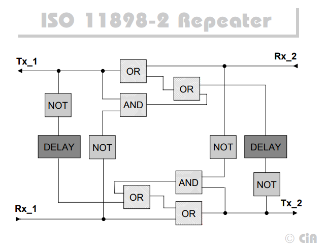
On Semiconductor manufactures the AMIS-42770 IC which can be configured to act as a CAN bus repeater with little external circuitry.
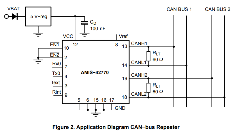
Application diagram from the AMIS-42770 IC’s datasheet which shows how it can be configured to act as a CAN bus repeater.
Examples
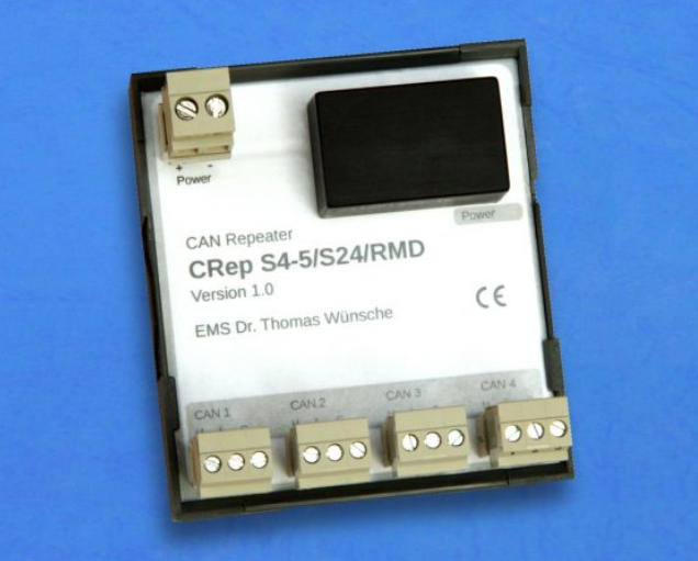
CAN Bus Repeater CRep S4 by EMS Wuensche
This device has 4 separate channels and is transparent to the other nodes on the CAN bus.
CAN FD Repeater Reference Design
A in-depth reference design by Texas Instruments which explains the inner-workings of a CAN bus repeater.
Link: http://www.ti.com/lit/ug/tidudb5a/tidudb5a.pdf?ts=1591658758534 local cached copy
One informative diagram in this document is the block-level architecture of the repeater:
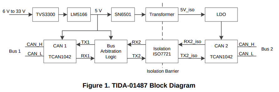
The block-level architecture of the CAN bus repeater design by Texas Instruments. Image from http://www.ti.com/lit/ug/tidudb5a/tidudb5a.pdf?ts=1591658758534.
USB to CAN Bus Dongles
There are many USB to CAN Bus dongles on the market. They allow you to connect a standard computer up to a CAN bus so that you can transmit/receive data and also measure statistics such as bus utilization.
One of the most popular CAN dongles is the PEAK PCAN-USB “CAN Interface for USB”. It supports CAN baud rates from 5kbps to 1Mbps19 and provides the CAN interface via a D-Sub DE-9 connector (pinout in accordance with CiA 303-1).
![Product photo of the PEAK PCAN-USB USB to CAN bus dongle[^bib-peak-pcan-usb].](https://blog.mbedded.ninja/electronics/communication-protocols/can-protocol/peak-pcan-usb-photo.jpg)
Product photo of the PEAK PCAN-USB USB to CAN bus dongle19.
CAN-FD
CAN-FD stands for CAN with flexible data-rate. CAN-FD is an extension of the classic CAN2.0 protocol, started in 2011 by Bosch. The physical layer is kept the same (voltage levels and signalling), but the packet structure is changed. Some of the big improvements over CAN2.0 is the increase in the maximum data size per packet from 8 bytes to 64 bytes20, and the ability to increase the bitrate 8-fold during the data transfer (which means a data transfer rate of up to 8Mbit/s!). The bit rate returns to normal during the second arbitration phase.17. Both of these serve to increase the bandwidth of the CAN bus.
Further Reading
If you are looking for help interfacing with SocketCAN from the Linux command-line, see the How To Use SocketCAN With The Command-Line In Linux page.
If you are looking for help controlling a SocketCAN interface from C software, see the How To Use SocketCAN With C In Linux page.
A alternative communications protocol used in similar applications is the LIN protocol.
References
Corrigan, Steve (2008). Application Report SLLA270: Controller Area Network Physical Layer Requirements. Texas Instruments. Retrieved 2021-10-11 from https://www.ti.com/lit/an/slla270/slla270.pdf. ↩︎
Bueno Electric. Maximum Cable Length For a CAN Bus. Retrieved 20221-10-11, from https://www.buenoptic.net/encyclopedia/item/537-maximum-cable-length-for-a-can-bus.html. ↩︎
OnSemi (2009, Jan). AND8376/D: AMIS-30660/42000 - Topology Aspects of a High-Speed CAN Bus. Retrieved 2021-10-11, from https://www.onsemi.com/pub/collateral/and8376-d.pdf. ↩︎
Griffith, John (2016, Jul 14). Why are termination networks in CAN transceivers so important?. Texas Instruments. Retrieved 2020-06-10, from https://e2e.ti.com/blogs_/b/industrial_strength/archive/2016/07/14/the-importance-of-termination-networks-in-can-transceivers. ↩︎ ↩︎
Ken Tindell (2023, Apr 3). CAN Injection: keyless car theft. CANIS CTO Blog. Retrieved 2023-05-01, from https://kentindell.github.io/2023/04/03/can-injection/. ↩︎
Elektromotus. Elektromotus CAN bus topology recommendations v0.2 rc2. Retrieved 2020-06-03, from https://emusbms.com/files/bms/docs/Elektromotus_CAN_bus_recommendations_v0.2_rc3.pdf. ↩︎
Richards, Pat (2001). AN754: Understanding Microchip’s CAN Module Bit Timing. Microchip. Retrieved 2021-10-11, from http://ww1.microchip.com/downloads/en/appnotes/00754.pdf. ↩︎
Taralkar, Meenanath (2012). Computation of CAN Bit Timing Parameters Simplified. CAN in Automation. Retrieved 2021-10-14, from https://www.can-cia.org/fileadmin/resources/documents/proceedings/2012_taralkar.pdf. ↩︎
J. A. Cook, J. S. Freudenberg. EECS 461 - Controller Area Network (CAN). University of Michigan. Retrieved 2022-11-17, from https://www.eecs.umich.edu/courses/eecs461/doc/CAN_notes.pdf. ↩︎
Kvaser. Kvaser CAN Protocol Course: CAN Error Handling. Retrieved 2022-04-07, from https://www.kvaser.com/lesson/can-error-handling/. ↩︎ ↩︎
port (2021, Feb 8). CanFaqErrors. Retrieved 2022-04-07, from http://www.port.de/cgi-bin/CAN/CanFaqErrors. ↩︎
CAN connected (2018, Aug 21). CAN Bus-Off condition/state. Retrieved 2022-04-07, from http://www.can-wiki.info/doku.php?id=can_faq:can_bus_off. ↩︎
CiA. CAN Physical Layer. Retrieved 2021-05-06, from http://www.inp.nsk.su/~kozak/canbus/canphy.pdf. ↩︎
Intel (1997, Dec). 82527 Serial Communications Controller Area Network Protocol. Retrieved 2021-10-14, from http://www.nj7p.org/Manuals/PDFs/Intel/273150-001.PDF. ↩︎
NXP. SECURCANTRLFUS REV 3 - NXP TJA115x Secure CAN Transceiver Family. Retrieved 2022-11-17, from https://www.nxp.com/docs/en/fact-sheet/SECURCANTRLFUS.pdf. ↩︎ ↩︎
Philips (now NXP). PCA82C200 - Stand-alone CAN-controller (datasheet). Retrieved 2022-11-23, from https://pdf1.alldatasheet.com/datasheet-pdf/view/87716/PHILIPS/PCA82C200.html. ↩︎ ↩︎
ST Microelectronics (2019, Oct). AN5348 - Application Note - FDCAN peripheral on STM32 devices. Retrieved 2022-11-16, from https://www.st.com/resource/en/application_note/an5348-fdcan-peripheral-on-stm32-devices-stmicroelectronics.pdf. ↩︎ ↩︎
Design & Reuse. CAN Bus Controller with Message Filter (Mailbox concept). Retrieved 2021-05-06, from https://www.design-reuse-embedded.com/product/auto_canmodule-iii_01. ↩︎
PEAK. PCAN-USB: CAN Interface for USB (product page). Retrieved 2022-04-07, from https://www.peak-system.com/PCAN-USB.199.0.html. ↩︎ ↩︎
CiA. CAN Knowledge > CAN FD - The basic idea. Retrieved 2022-11-16, from https://www.can-cia.org/can-knowledge/can/can-fd/. ↩︎
Authors


This work is licensed under a Creative Commons Attribution 4.0 International License .
Related Content:
- How To Use SocketCAN With The Command-Line In Linux
- PROFIBUS
- Consistent Overhead Byte Stuffing (COBS)
- PID Tuner Tool Released In NinjaCalc
- LVDS (Low-Voltage Differential Signalling)
Tags
- CAN bus
- bus
- communication protocol
- CAN1.0
- CAN2.0
- CAN base frame
- CAN extended frame
- USB adapters
- NoCAN
- encoding
- controller
- CANopen
- NEMA 2000
- termination resistors
- FlexRay
- SAE
- J1850
- J1939
- ISO 11783
- ISOBUS
- isolation
- mailboxes
- CAN-FD
- NXP
- Secure CAN