Switched-Capacitor Circuits
| Date Published: | |
| Last Modified: |
Overview
Switched-capacitor circuits are circuits which move electronic charge in and out of capacitors using electronics switches. They are commonly manipulated to make a “tunable” resistance which depends on the switching frequency. They are used in circuits such as switched-capacitor filters and charge pumps.
The basic switched-capacitor circuit is shown below:
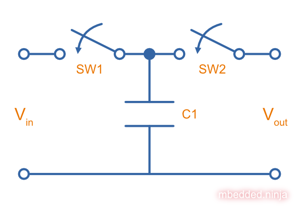
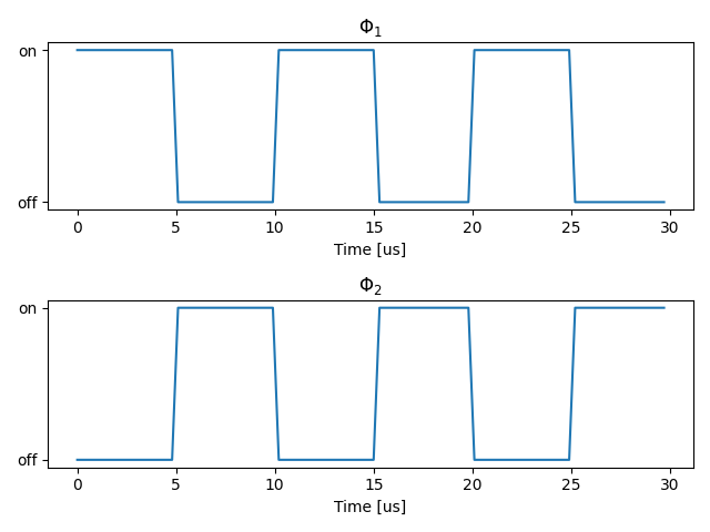
The switches are switched on/off in an alternating fashion, where \(\Phi_1\) controls SW1 and \(\Phi_2\) controls SW2. This is shown in the below graph. A switching frequency of \(100kHz\) is assumed.
Equivalent Resistance
By changing the switching frequency, you can change the equivalent “resistance” between \(V_{in}\) and \(V_{out}\). The equivalent resistance is:
$$\begin{align} R_{equiv} &= \frac{1}{C_1f} \\ \end{align}$$This is the core principle behind switched-capacitor filters.
Equivalent Resistance Derivation
In phase 1 when switch SW1 is closed and SW2 is open, the capacitor charges up to \(V_{in}\). By definition, the charge stored in the capacitor during this time is:
Similarly, in phase 2 when switch SW1 is open and SW2 is closed, the capacitor charges up to \(V_{out}\). The charge stored in the capacitor during this time is:
So the change in charge is:
$$\begin{align} \Delta Q &= Q_1 - Q_2 \nonumber \\ &= C_1V_{in} - C_1V_{out} \nonumber \\ &= C_1(V_{in} - V_{out}) \nonumber \\ &= C_1\Delta V \\ \end{align}$$Now, current is defined as change in charge over the change in time:
$$\begin{align} I = \frac{\Delta Q}{\Delta T} \end{align}$$Assume the switching period \(\Delta T\) is the total time of phase 1 and phase 2. The switching frequency is just the reciprocal of this, so:
$$\begin{align} I = \Delta Q*f \end{align}$$Substitute in \(\Delta Q\):
$$\begin{align} I = C_1 \Delta V*f \end{align}$$Finally, using Ohm’s law, the equivalent resistance of the switched-capacitor circuit is:
$$\begin{align} R_{equiv} &= \frac{\Delta V}{I} \nonumber \\ &= \frac{\Delta V}{C_1 \Delta V f} \nonumber \\ &= \frac{1}{C_1f} \\ \end{align}$$Realistic Implementation Using MOSFETs
Above we have just drawn in mechanical switches to show that the circuit is switched at these points. But how is the switching actually done in reality? A common approach is to use a MOSFET. They allow the circuit to be switched between their drain and source by applying a voltage on the gate. They offer two main benefits over BJTs:
- The drain and source voltages are not tied to the gate voltage in anyway (in a BJT, the base is tied to the emitter + 0.7V). This is a very useful property for the MOSFET to have.
- The gate requires almost no current to drive, whilst a BJT requires a small but sometimes non-insignificant base current.
However, a single discrete MOSFET is rarely ever used because the internal body diode will conduct in one direction when not desired, and the switching resistance of the MOSFET rapidly increases as the signal voltage nears the gate voltage, which is typically at \(V_{DD}\) for N-channel MOSFETs and \(0V\) for P-channel MOSFETs.
To overcome both of these challenges, typically complementary non-discrete N-channel/P-channel MOSFET pairs are used to make an analogue switch1. The complementary pair allows rail-to-rail signals without significant resistance increases, and using non-discrete MOSFETs allows the semiconductor designed to connect the substrate to the rails rather than to the source, preventing the “body diode” conduction effect in one direction.
References
UCLA. Chapter 12: Introduction to Switched-Capacitor Circuits. Retrieved 2022-09-19, from http://www.seas.ucla.edu/brweb/teaching/AIC_Ch12.pdf. ↩︎
Authors


This work is licensed under a Creative Commons Attribution 4.0 International License .
Related Content:
- August 2015 Updates
- April 2016 Updates
- February-June 2014 Updates
- Skateboard Motion Sensor And Alarm Prototype Working
- Electric Skateboard Half-Bridge Mach 4 Almost Working